Line Isolation Monitor

You can buy a LIM for $1000-$2000, which is a great deal for a hospital operating room but a bit stiff for a sailboat where nobody dies when AC power is disrupted.
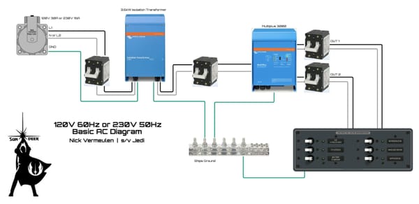
A couple remarks before diving in: the diagram above is conceptual, not an actual schematic, which requires more components. Also, there always exists a galvanic connection between L1 and L2, which happens in a winding of a transformer, generator, or in the output stage of an inverter. The resistance here is very low (typically 0.1 Ω) compared to the mega-ohms of resistance we use for measuring and thus we ignore it.
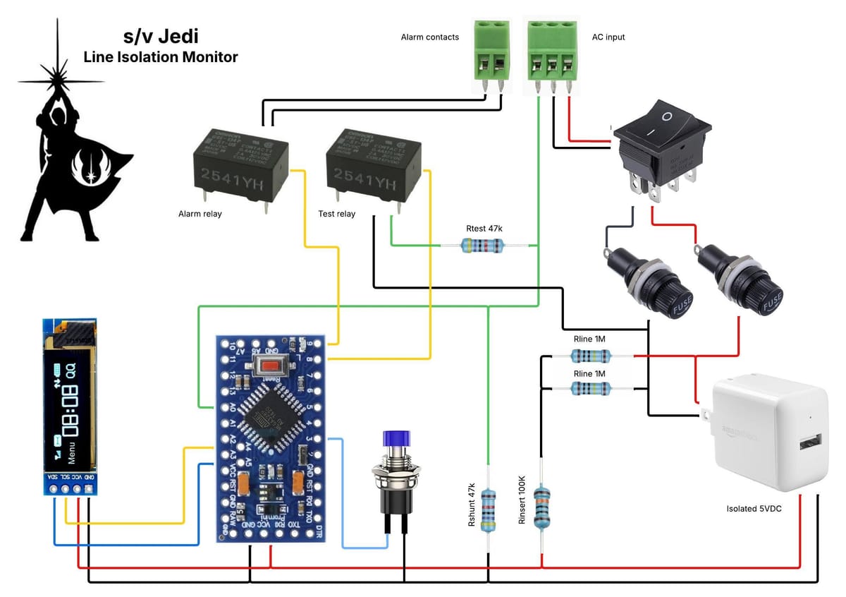
Let's start at the upper right where we have a 3-position terminal to connect to our AC power. L1 and L2 go through a double-pole switch and fuses. After the fuses is an isolated 5V DC power supply as well as two resistors of 1M each which are interconnected at a point I call S.
The 5V DC powers the microcontroller (MCU) and its small OLED display. It is also injected into the AC wiring using a 100k resistor between the positive and S and a 47k resistor "R-shunt" between the negative and P. There should not be any connection between P and S, so no current should flow and there should be no voltage drop across R-shunt. The microcontroller is monitoring voltage across R-shunt.
Now an example of something going wrong: our toaster oven develops a short between L2 and P. From our +5V we first have a 100k resistor, followed by two 1M resistors that are parallel for DC so become 500k, total 600k. In the negative we have another 47k shunt resistor so our total becomes 647k. At 5V this means we get 5/647k=7.73µA which is almost nothing. But this does create a 7.73µA x 47k = 0.363V which is perfectly measurable for the 10-bit ADC with the 1.1V reference that the MCU has.
We want to be able to measure not just a short between L1 or L2 and P but also a degradation of isolation long before it becomes a short. You often hear that a safety triggers at 5mA. The reason is that 5mA is already in the range where AC shock current becomes dangerous. A 47k fault path corresponds to 5mA at 235V. This is why we use a 47k test resistor, and we connect it between L1 and P to verify correct operation. At 5mA and 235V it must be able to dissipate about 1.2W, so in practice this should be a 2W resistor. Connecting this resistor is done with a test relay that is controlled by the MCU.
During startup the MCU first measures the shunt and expects near 0V. Next it inserts the test resistor between P and L1 and measures again. What should it see? 647k plus the extra 47k resistor is 694k, so the current is 5/694k=7.2µA instead of the 7.73µA we had with a hard short. The MCU measures 47k x 7.2µA = 0.339V instead of 0.363V. Now the MCU can calculate everything and calibrate itself, for example, raise the alarm at 0.335V or higher. For measurements between 0V and 0.335V it can show the degradation on its display.
There is a manual pushbutton switch connected to the MCU. A long push could be used to close the test relay for the duration of the push, allowing manual tests. We can also implement short and/or double-push actions for other functions using the display for feedback.
The last major component is an alarm relay that is controlled by the MCU and has its contacts on the second terminal block. Here we can connect something simple like a buzzer, or something more elaborate like an alarm module (Victron Cerbo digital input for example).