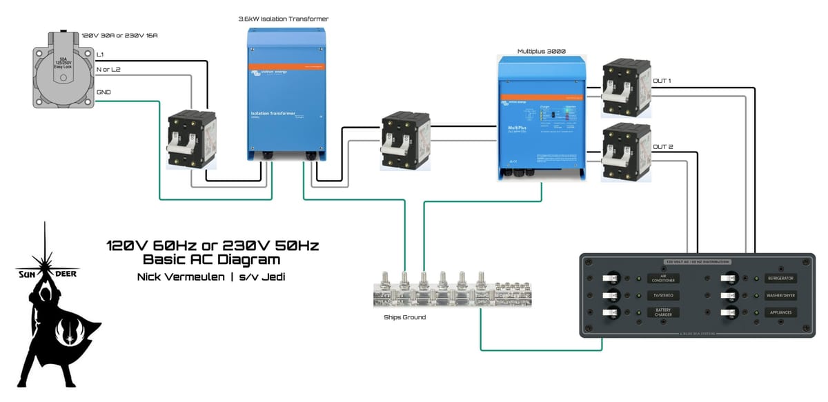
Basic AC power diagram

I made this diagram years ago and posted it on the Cruising Forum. The problem there is that it simply is too hard to find and it gets lost, so I’m posting it here instead.
The goal of all my diagrams is to be a reference and this is the most basic version of an installation that I made. Yes, it has an isolation transformer because that is what you should have when you install a shore power option. It doesn’t make sense to skip it as the cost, time and effort is nothing compared to what you get: 100% safety for the people on and around the boat incl. swimmers, as well as perfect safety for the underwater metals of your boat. It’s better than an insurance policy.
Between the shore power inlet and transformer you see a simple double pole breaker. Here you win back most or all of the cost of the transformer because you need an expensive ELCI breaker that can cost up to $400 and only partly protects against electrocution.
Here are the most important things to do after wiring this installation:
- Using a digital multimeter, check that none of the three input conductors have a galvanic connection to any of the transformer output conductors. For example, input Neutral should have no connection to output Ground, no connection to output Line/Hot and no connection to output Neutral. Repeat for every input conductor.
- The transformer comes with a jumper to connect input ground to output ground. Do NOT install that. Technically, you should simply throw it away as it has no functionality, but legally you should install it when you use shore power while in the hard. The problem is that you are likely going to forget removing it before going back in the water again!
- The transformer comes with a jumper to connect the output Neutral to output Ground. When you install it, you get a grounded neutral and you can have single pole distribution breakers. So when you have single pole distribution breakers then you have no choice and must install it. That said, many boats built outside the US do have double pole distribution breakers and now you can choose to not install this jumper. Read my articles on this here on this blog.
- The diagram shows a ground busbar which I call Ships Ground. This is a central ground busbar which interconnects all AC power ground wiring EXCEPT the ground conductor from the shore power inlet. When something is not connected to it in the diagram then don’t connect that to the diagram: do not connect underwater grounding plates, do not connect the engine, do not connect your batteries etc. All the rules that say this must be done is for installations that do not have isolated power. Code has exceptions for it or they are being worked on.
You may want an underwater grounding plate for other reasons, like lightning protection or bonding systems with zinc anodes etc. Just remember that your isolation transformer has isolated your boat AC power from ground so don’t connect it to ground in any other way. - If you have a floating system then it is correct that the test button on GFCI outlets doesn’t work. The reason is that you can’t be electrocuted via ground because your AC system has eliminated ground as a return path, which is why it is so safe. This is why you don’t need GFCI outlets anymore. The test button is a momentary switch that connects the Line/Hot with a resistor to the ground wire, causing a current to flow through the Line and Ground conductors but not through the Neutral conductor. As the GFCI compares the current flowing through Line with the current flowing through Neutral and when the difference is larger than the rating, it breaks the connection. Of course the resistor is dimensioned to trigger that condition in order to test the outlet. But with a floating system, pressing the button does not cause any current to flow, demonstrating that this protection system isn’t needed.
When I find other points people need more or better explanations for then I will update this post.