Jedi BMS v3

Last year I designed BMS v2 and built a prototype that worked great. I continued to design the circuit boards, finished that and then never actually ordered them… because I didn’t like the large size and mass of cabling.
What I liked about the design is that it uses the SensESP library to integrate with SignalK which can run on a Victron Cerbo GX or a dedicated SignalK server. It links to the Victron battery monitor or SmartShunt that writes battery data to SignalK and adds details about individual cells and the status of the Remote Battery Switch (RBS) for which I recently designed and built the cradle with communication interface.
What I didn’t like is that I used an INA226 board for every cell which was already crazy with 8 cells and I didn’t see how it would scale to 16 cells for a 48V battery. The wiring was a mess as well.
I decided to abandon my plans for a single INA226 or ADC with a multiplexer in front and go for cell boards again with daisy chain wiring just like the RBS modules I just designed, using RJ11 phone cables. This means that there’s just a single 4-conductor phone cable from the main controller to the battery cells to measure everything, regardless of the nu of cells.
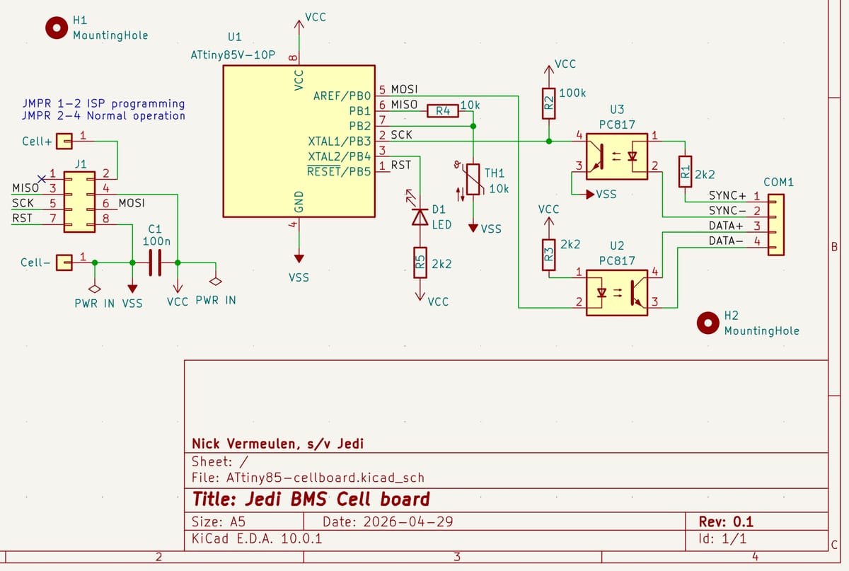
I selected a low voltage version of the famous tiny microcontroller, the ATtiny85V-10PU which can work down to 1.8V which is well below the 2.5V minimum voltage of a LiFePO4 cell.
The cell boards will communicate with a central controller which is still the same ESP32 with POE Ethernet. This communication must have galvanic isolation because the cell boards have their ground at the negative terminal of the cell they monitor, which can be a high voltage. I selected basic optocouplers for this and a 2-way bus protocol:
The ESP32 sends out a periodic Sync followed by shorter data requests. These are simple pulses: a long 100ms pulse for Sync and short 20ms pulses for data requests. In between periods the controller goes into power saving sleep mode.
The cell boards are also in a power saving sleep mode where only a hardware interrupt can wake them from. This is the rising edge of a pulse from the ESP. The Interrupt Service Routine first determines if this is a long Sync pulse by waiting 40ms before checking if the pulse is still at high level. If so, it clears all its data and counters and measures cell voltage and temperature which is stored with a checksum, before going into sleep again.
If the ISR finds a short pulse, it increases a cell number counter. If the new number is not the cell number that it monitors, it goes to sleep again; if it is a match then it transmits the measured data with checksum to the ESP, then goes back to sleep.
The ESP collects all the data and writes it to SignalK, while also checking if everything is okay. It can send out warnings if not or even take the battery offline if needed.
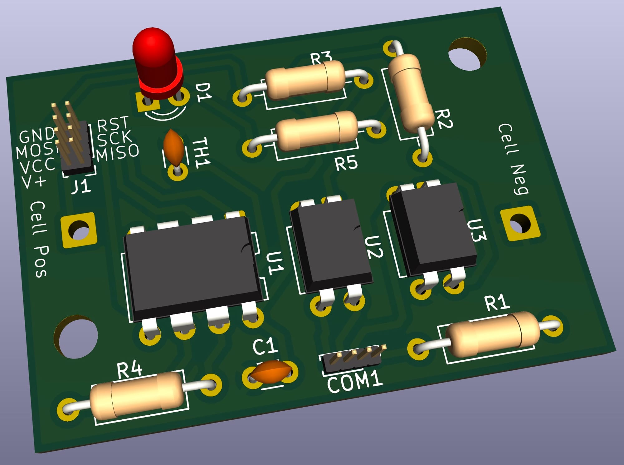
The ATtiny85 will be soldered onto the cell board, which has a connector for In System Programming. The board is then connected to a 3.2V reference power supply and we find the calibration data for the voltage measurement as well as the temperature measurement. That calibration data, as well as the cell number it must monitor is written into its internal EPROM. After that it is reprogrammed to its regular firmware.
Of course there will be a 3D printed housing with two RJ11 jacks for daisy chaining the communication bus. Wires for connecting to the cell terminals with an inline fuse are directly soldered to the circuit board. The thermistor will poke through the underside for contact with the cell and the LED will be visible behind a transparent window in the polycarbonate lid. I plan to use VHB tape for mounting and a thermal pad for good thermal contact of the thermistor.