AC power diagram part 1

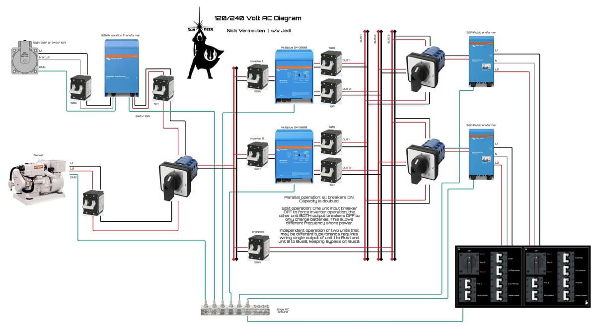
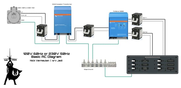
For these posts I am using a diagram that closely follows our actual installation aboard Jedi. In this post I discuss the input side: the shore power and generator inputs, the transfer switch, the input bus and the P conductor busbar.
I present a detailed description of an installation that represents best practice and conforms to codes and guidelines where possible. That does not mean it is the only allowed way: if your setup does not meet the constraints I describe, ask a professional installer to come up with alternatives that still comply with code. I also use components and methods that ABYC, and probably others, have not fully caught up with yet.
Shore power
Shore power is much more dangerous than most sailors realize. Think of your boat as a plugged-in toaster lowered into the bath. That highlights the personal safety aspect, but there is also the risk of galvanic corrosion of underwater metals, from the propeller to, in the case of a metal boat, the hull itself.
While most installations are based on reducing costs as much as possible while barely conforming to code, our installation addresses all these dangers in a decisive way. Instead of using tricks to reduce risks, we choose to eliminate them, even when that adds a little cost.
This is why we do not use a galvanic isolator, which is really a trick using diodes to block most cases of galvanic corrosion. The problems with it are many: the diodes can fail without being noticed, or be overwhelmed in severe cases, so galvanic corrosion can still keep eating away at your boat. It also adds nothing to personal safety, and that is putting it generously, because it is barely allowed and can in some cases actually increase risk.
We must install the isolation transformer as close to the inlet as possible (ABYC: within 10’), which allows us to eliminate expensive safety devices like ELCI breakers, recovering most if not all of the cost of the transformer. Instead we can install a standard double pole breaker. As we use a 3.6kW transformer and input voltage can be as low as 110V, we use a 30A or 32A breaker.
The output is always 230/240V so here we use a 15A or 16A breaker. I recommend to use 10AWG marine wire for all these connections with crimped ferrules at the terminals.
Take a good look at the transformer in the diagram: left has three conductors going in: none of those may have a connection to any of the three conductors coming out at the right. This is the 100% isolation: the input from shore powers a magnetic field inside de core of the transformer and that magnetic field is the only coupling with the secondary windings and the rest of the boat.
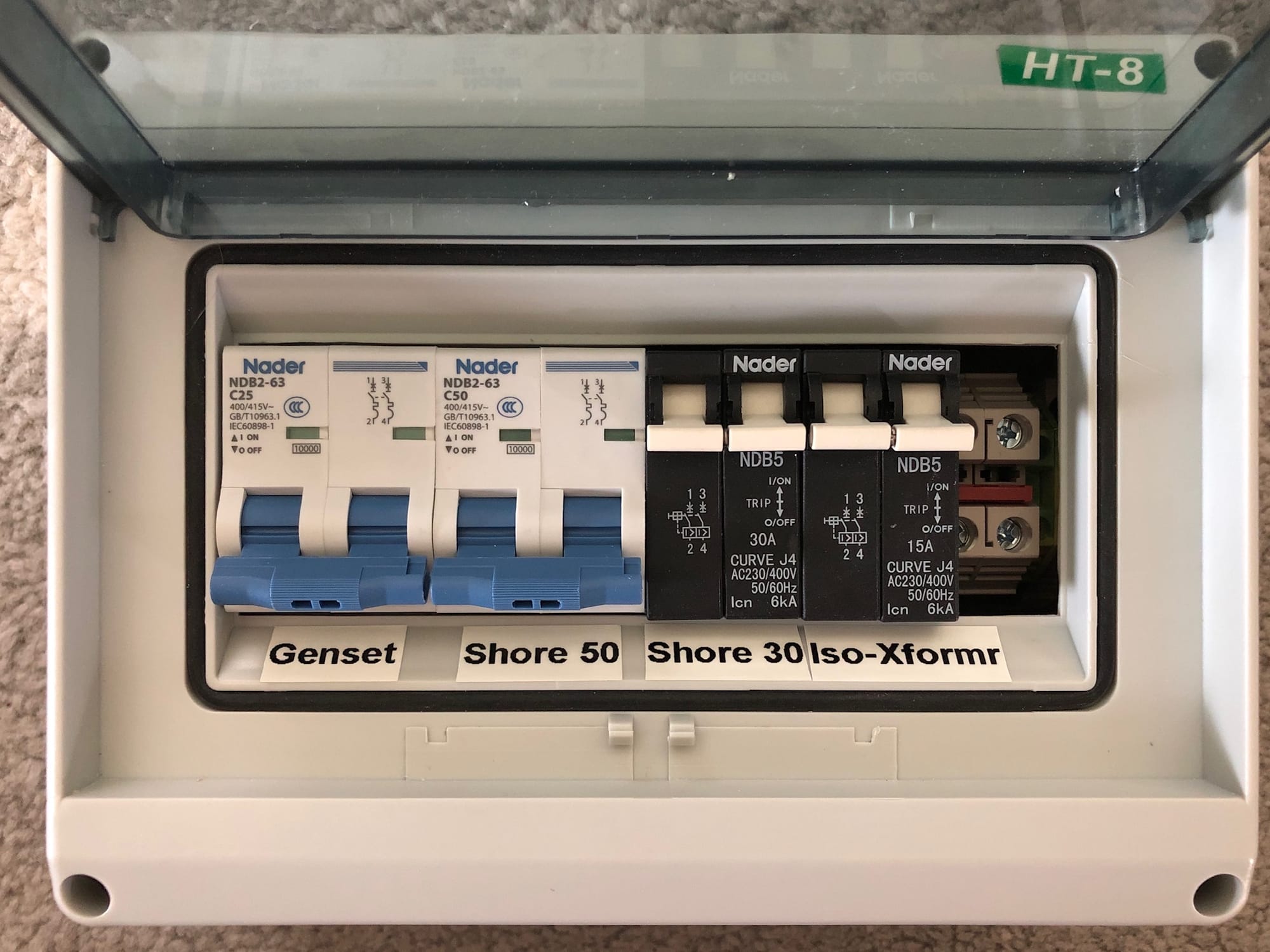
In the picture below we have a DIN rail breaker box with the 30A and 15A breakers for the shore power, as well as the generator and a second shore power connection that isn’t part of the diagram. On the right you can see some DIN rail terminal blocks where the P conductor connections from shore power and generator connect. I removed the cover over their position to make it easy to reach with a test probe to check isolation.
Generator
When we have a generator with electric start, we introduce a major complication: these units use the engine block as the DC return for both the starter motor and the alternator. The engine block is also commonly connected to the PE output terminal, so this means our protective conductor may end up connected to DC negative.
I believe this is what ABYC will eventually recommend, or even require, so let’s look at what this means. We still have an isolated floating AC system, so P has no intentional connection whatsoever to the AC power-carrying conductors. But by connecting P to the generator engine block, it may also become connected to the main engine block, which may in turn be connected to the propeller shaft. That brings the boat’s underwater metals into close proximity to our AC power.
To minimize the impact, we will use a double-pole DC isolation switch for the generator and keep that switch off whenever the generator is not in use, which for us is for very long periods.
While outside the scope of this topic, I recommend doing the same for the main engine, so that DC negative is isolated from underwater metals as much as possible when the engine is shut down.
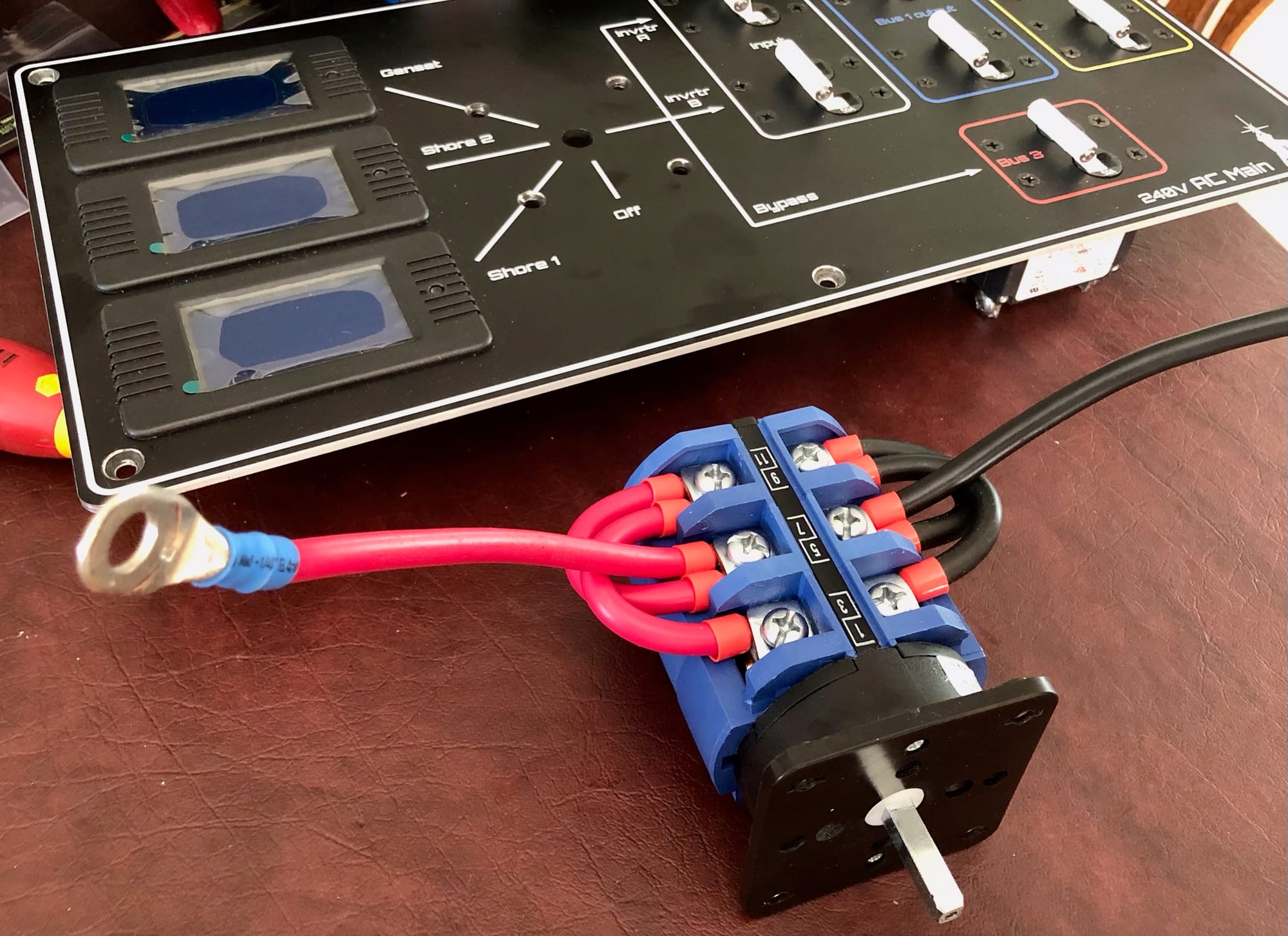
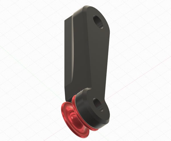
Double pole transfer switch wiring and mounted in main AC panel
Transfer switch
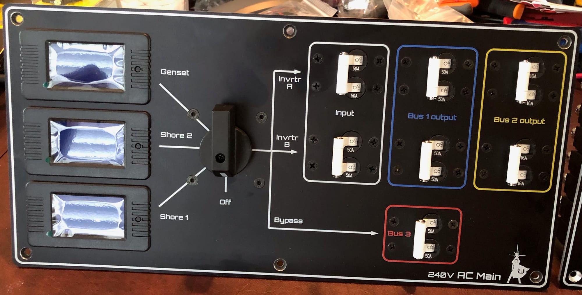
This brings us to the transfer switch, which must also be a double-pole switch. I prefer to have this switch at my main AC switch panel, which I specifically designed for this AC power system. That means we need separate wiring runs from each input source to this switch. I use AWG8 wire for these runs to minimize losses as this can be a rather long distance.
Having all these wires come together at the switch also makes it easy to add power monitors for each input, mounted on the same panel. This allows us to see how many kWh of shore power we use if we need to check the bill, and how much power comes from the generator if we want to know how much additional solar power we need.
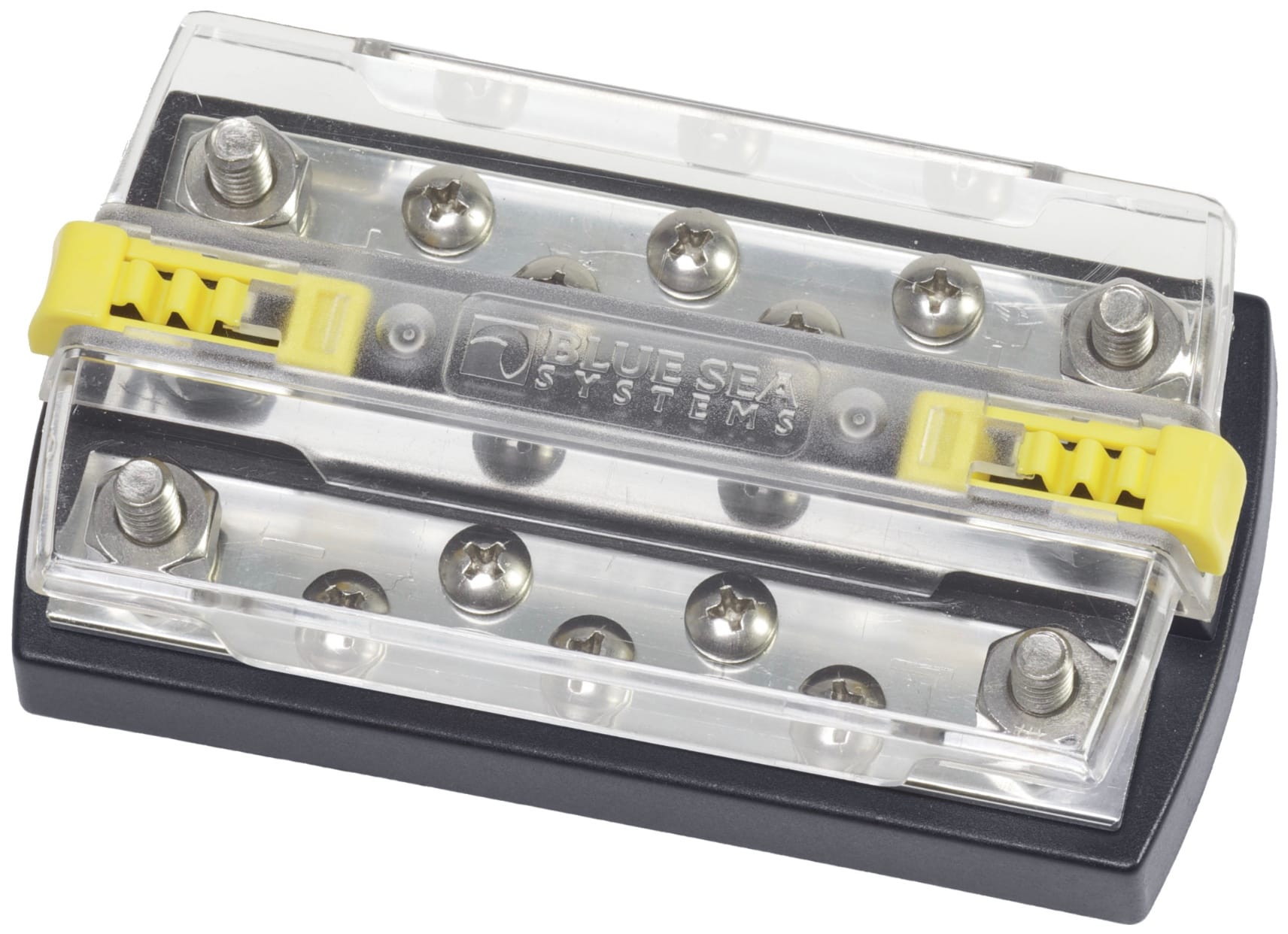
The output of the transfer switch goes into the input bus, from where breakers feed the inverter/chargers and a bypass. You can buy dual busbars for this that have a safety lid like the picture below. We also use these dual busbars for the output busses as well as for the distribution panels.