AC power diagram part 2

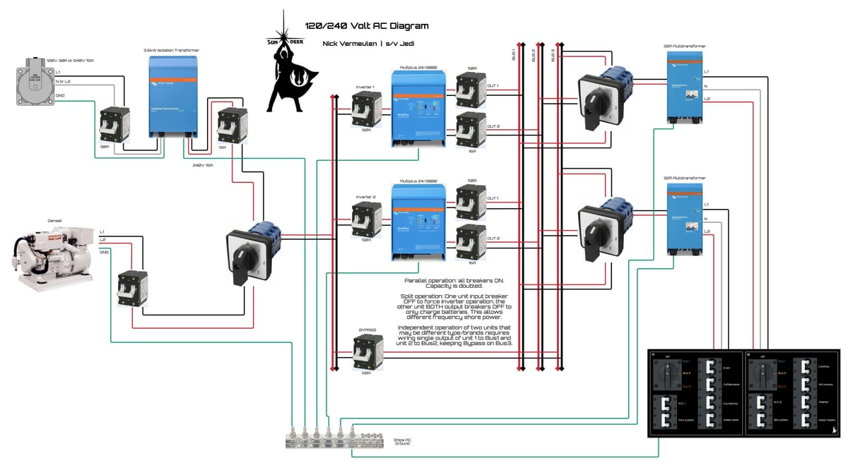
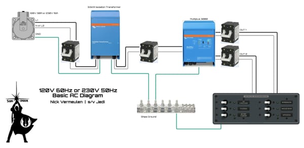
In part one we arrived at the input bus where incoming AC power, if any, is present. This incoming power is used to charge the batteries and/or to feed the distribution panels for use throughout the boat.
Multiplus inverter/chargers
I recommend two identical units that are special-ordered from a dealer to be able to work in parallel service. They must be the same hardware revision and have the same firmware. There’s several models to choose from, which mostly depends on your generator: when your generator is 8kW or more then you can choose the Multiplus 3000 with 50A transfer switch or Multiplus II 5000 with a 50A transfer switch; under 8kW you can also opt for the Multiplus II 3000 model with 32A transfer switch.
You must make sure you get the 230V model with the correct transfer switch and of course the correct battery voltage: 12V, 24V or 48V. I recommend 24V at the time of this writing, but when al the announced 48V DC-DC converters come out, 48V becomes the recommendation. If your boat is 12V when you are making the choice of lithium battery voltage then consider that 12V is barely possible and requires the heaviest gauge, very expensive wiring. Simply get two large DC-DC converters going from 24 to 12V or from 48 to 12V. If you have a 24V boat then I recommend to keep 24V as it is good enough for the power levels we work with.
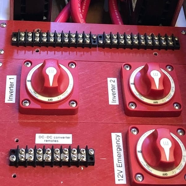
Each Multiplus gets an input breaker connecting it to the input bus. This breaker must be double pole and the same value as the unit’s transfer switch. The diagram shows that both outputs of the units are connected: OUT1 to Bus1 and OUT2 to Bus2. This is the setup that allows parallel operation which is my recommendation. Another option is to connect OUT1 of the first unit to Bus1 and OUT1 of the second unit to Bus2, which allows independent operation, even from different brands of units.
Now we get to some of the functions of this setup: if a Multiplus has all its input and output breakers switched on, it can charge the batteries, pass input power on to the output busses and invert from battery power to AC power. It’s PowerAssist feature allows it to add its maximum inverter output to incoming power. With two 3000VA models and a 6kW generator this means we can power up to 12kW. With shore power we can power up to 9.6kW and with just batteries up to 6kW. This should be plenty for most cruising sailboats.
If we switch the output breakers of a Multiplus off and its input breaker on, we have configured it as a battery charger only. If we switch the input breaker off and the output breakers on, we configured it as an inverter only.
This brings us to an advanced setup where we configure one unit as charger and the other as inverter. Now we have reduced our AC power to that of one unit but we can convert a foreign frequency shore power to the correct frequency we use aboard.
Output busses
A configuration where the Multiplus outputs are connected in parallel is only possible when the units are configured to work in parallel service. Keep the output breakers OFF until that configuration is complete. You need Victron configuration software for this which is available for free, plus a Mk3 USB adapter to connect a laptop to the units. Both Multiplus units will work as if it’s a single unit of double power.
On Bus3 we only have a simple bypass breaker. This means it only receives power if there’s power on the input bus. This is much like the OUT2 of the Multiplus units except you don’t need them and they could be fully switched off or even removed. This is useful for powering a water heater, A/C or when the boat isn’t used, for a dehumidifier. The bypass allows power distribution during maintenance, equipment failure etc.
An advanced setup is again for foreign shore power that has a different frequency. Many high power appliances can run on different frequencies so you could have the foreign shore power frequency on Bus3 while having one Multiplus charging batteries from that same foreign shore power and the other Multiplus inverting to Bus1 for our boats native AC frequency. This is more efficient than it seems because the DC output from the first Multiplus is directly transferred to the other Multiplus that is inverting, skipping the battery.
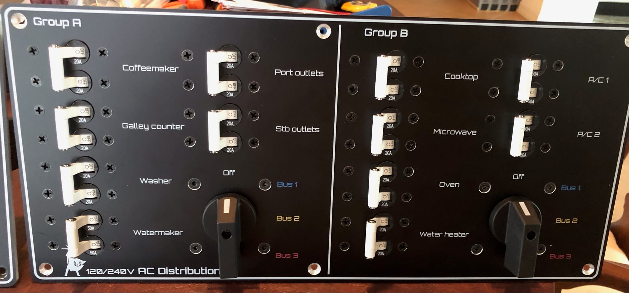
The three output busses are wired to one or more distribution panels or, like I did, one panel with two independent groups. Each panel/group has an input selector for choosing Bus1, Bus2 or Bus3. Look at my panel closely: group A has distribution breakers to appliances that all are likely to be running on inverter power, while group B are much less critical and when power generation is low (overcast skies, low solar power), could be switched to Bus2 or Bus3 to only receive power when the generator is running.
The distribution input selector is a two pole rotary switch and its output is connected to a new pair of L1 and L2 busbars that are used for wiring to the distribution breakers.
120V
For American boats we have the issue that we’re still on 240V power. We fix this by inserting an auto transformer between the distribution panel input selector switch and the distribution bus bars, of which we now need three instead of two because we have the additional center tap.
we can have three different types of breakers on the distribution panel: we have 240V breakers that connect to L1 and L2; we have 120V breakers that we connect to L1 and the center tap and last is 120V breakers that we connect to L2 and the center tap. Try to balance loads over L1 and L2 as good as possible. Any imbalance will be handled by the auto transformer up to its 32A maximum. Example: 120V breakers connected to L1 pull 20A while 120V breakers connected to L2 pull 8A. The difference, 12A is handled by the auto transformer.
Now here’s what makes this setup superior: the 240V input of the transformer in this example will be 14A (20+8)/2 and perfectly balanced for the output of a transformer or generator. You can always get maximum power, even when it’s not perfectly balanced.
If you have a distribution panel that is 240V only, you can omit the auto transformer. An example is a panel in the engine room with circuits to 240V water heater, water-maker and air conditioner.
Wiring sizes
The branch circuits to outlets etc. are normally AWG12 which can be used up to 20A. For 30A go up to AWG10, for 40A use AWG8 and for 50A use AWG6. For long runs, go up one size; on Jedi we use AWG6 for a 50A run of 8 meters without trouble.