AC power setup for sailboats

Now that we have solar arrays, lithium batteries and good electronics to run everything, it is time to upgrade the AC part of our systems to a safer and better setup.
This better system is insulated floating power distribution, like used in hospitals, war ships and commercial ships and other installations where continued power availability is important. These insulated power systems are defined in code, and ABYC is working on standards for modern recreational marine use.
I have written about this before and decided to pick it up this time by describing it in more detail and designing a Line Isolation Monitor (LIM) that doesn’t cost as much as the commercially available ones. I come back to the LIM later.
This document will include both 230V systems as used in most of the world and 240/120V systems as used in the US. The setup and hardware used are almost identical. For the US system only one additional device, an auto transformer is used and you get both voltages and perfect balance, allowing full power utilization from generator and inverters.
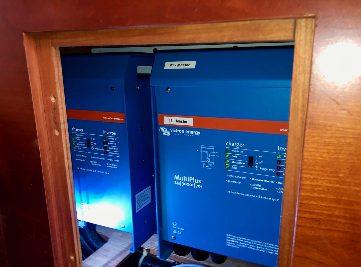
I use Victron components in this document because they are common and have the features that are required.
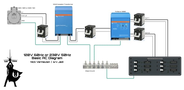
We start the system by describing three conductors that connect to the input and output terminals of the central inverter/charger(s).
L1 is a power-carrying conductor. It is not grounded.
L2 is a power-carrying conductor. It is not grounded.
P is a protection conductor. It is not grounded.
For EU-based systems, we have 230V 50Hz between L1 and L2. For US-based systems this is 240V 60Hz. P has no connection to L1 or L2. Note that there is no neutral conductor.
We use the Victron MultiPlus 230V units and a MK4 USB programming dongle. The first setting we change is the AC ground relay, which we disable. For a US system we also change the inverter output to 240V and 60Hz. Enable the Dynamic Current Limiter and the Power Assist modes.
With a US system, we connect the AC output of the MultiPlus to a Victron 32A autotransformer. We do not connect the grounding relay. What remains is a winding between L1 and L2 with a center tap labeled N, which we use much like neutral, except it is ungrounded.
In our distribution breaker panel we can now have both 240V and 120V breakers, and these must all be double-pole breakers. Connect half of the 120V breakers to L1 and N and the other half to L2 and N. Try to balance these: any imbalance must not be greater than the 32A rating of the autotransformer. Look at the high-power appliances like cooktops, ovens, air conditioners, water maker etc. You will find it is rather easy to balance it logically and not difficult to keep imbalance below 32A.
With an EU system we don’t need the autotransformer, so we simply connect all double-pole breakers to L1 and L2.
We use a bus bar for all the P protection conductor connections.
Shore power
Shore power must also be ungrounded and floating on the boat side. This is only possible by using an isolation transformer.
Our modern system with lithium batteries and PowerAssist from the MultiPlus only requires shore power to cover the average power consumption. During high power usage, shore power is supported by battery power, and during lower power usage the batteries are charged again.
This means a Victron 3.6kW isolation transformer is adequate. Using the internal jumpers, we connect the output windings in series for a fixed 230/240V output. We also remove the grounding jumper.
For 230/240V input we connect the input windings in series. If we can only get 120V input, we connect the input windings in parallel so that the transformer doubles the voltage. There is also a version of this transformer that can automatically switch the input windings.
The important part is that none of the input terminals may have any connection to any of the output terminals. Test this before, during and after installation.
The isolation transformer requires a 30–32A double-pole breaker on the input and a 15–16A double-pole breaker on the output. The input PE connects to shore ground, while the output PE connects only to our onboard protection conductor P.
Generator
The generator must also be ungrounded and floating. In most cases this means you must remove a grounding jumper in the generator connection box: use a multimeter to check that the PE/Ground terminal is not connected to N, and also not to L.
For US systems you may find that you have a 120V generator instead of 240V. Inboard diesel generators can normally be reconfigured for 240V. As with the isolation transformer, there will be two output windings that are connected in parallel and must be connected in series instead. Often there is also a voltage regulator with a 120/240 jumper that needs to be moved.
If you have a portable 120V generator, it may be an inverter-type unit that cannot be changed to 240V. In that case you connect it to the shore power inlet, so that the isolation transformer can double the voltage.
Safety mechanism
So why is this system safer and better for a boat? First is the higher availability of power. In a traditional system we have a grounded neutral. This means that neutral is already connected to the metal surfaces of appliances. When we develop a short between L and the metal housing, we also have a short between L and N and the breaker trips, causing loss of power.
With our setup, we do not lose power on the first insulation fault. Instead, the Line Isolation Monitor gives an alarm. We only lose power when both L1 and L2 develop a short to the metal surfaces, which is much less likely.
When the LIM sounds this alarm we still have power and can fix this fault (disconnect an appliance to see if the alarm stops which identifies the faulty appliance) and prevents loss of power if a second fault develops.
We have also eliminated ground as a return path for completing a circuit. A traditional system has N connected to ground, so when we touch L while standing on a wet floor or otherwise connected to ground, we can get electrocuted. Hopefully we have a GFCI outlet or other protection that detects this and trips a safety device.
Our setup greatly reduces this risk because there is no intentional connection to ground. That said, it is still important to understand that a floating system is not magic: leakage, moisture or a second fault can still make the system dangerous. That is why the Line Isolation Monitor is essential.
This isolation from ground has another advantage for a boat: the power system is isolated from the underwater metal parts of the boat like a propeller, rudder stock, shaft, strut and thru-hull fittings. This means there is no galvanic corrosion caused by the ungrounded system.
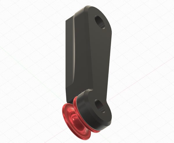
Line Isolation Monitor
This is an additional safety device that continuously monitors the galvanic isolation of the P protection conductor from L1 and L2. This means we get an alarm when the isolation between P and L1/L2 becomes bad enough that more than 5mA would flow if the other conductor also shorted out to P. So this monitor is much more precise than just checking for a full short, increasing safety even more.
We can’t do this monitoring by just measuring voltage, because we have inductive and capacitive couplings in wiring and appliances that cause “ghost voltages” on the P conductor that would fool a voltmeter. To eliminate false alarms, we inject a test signal and monitor that continuously. This test signal is an isolated 5V DC supply, which also powers the microcontroller and display of the LIM.
Internally we use a resistor network to connect the +5V measuring voltage to both L1 and L2. We use a single resistor to connect the measuring voltage negative to P, and the microcontroller measures any voltage over that last resistor, which acts as a shunt. When any galvanic connection between P and either L1 or L2 develops, even a tiny one from moisture or corrosion, a small DC leakage current starts flowing and we measure a voltage over the shunt resistor.
For calibration and testing we can create a deliberate isolation fault by connecting a resistor between L1 and P. We use a value that would create a 5mA current at the system voltage, which is about 200 times the voltage in Ohms, i.e. 47kOhm for our 230/240V system. When the LIM starts up, it uses a miniature relay to create this test fault and compares the measured voltage with the normal measurement, which should be zero. This startup test checks that the monitor is working correctly and is used as a calibration reference for the alarm value.
There is a manual push button in parallel with the relay so that we can press it at any time and check that this results in an alarm. As we use a microcontroller we gain full software control over this. The alarm is visual and audible with a mute button, and a second miniature relay provides alarm contacts for connecting to other systems.
Updates on this subject will include detailed diagrams as well as the LIM circuit diagram and circuit board, test results etc. I already have this floating isolated power system aboard Jedi, but not a LIM yet.