Building prototype cell board

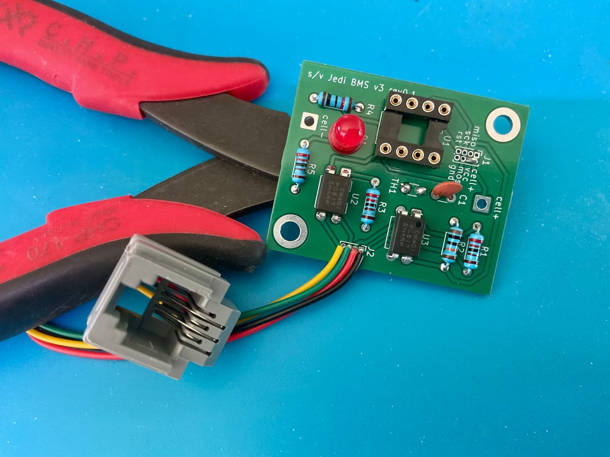
We’re back in Florida so projects can resume! Surprisingly I had enough parts to build one complete cell board, which is now ready for testing. The empty DIL-8 socket is for the ATtiny microcontroller, which I program out of circuit.
The RJ11 socket is for connecting these boards in a daisy chain to each other and the controller board. So there’s the first mistake: each cell board needs two RJ11 sockets but I don’t think the PCB header connections are large enough for two wires… I need to make these headers larger and add an extra one for the second RJ11. For now I’ll find a way ;-)
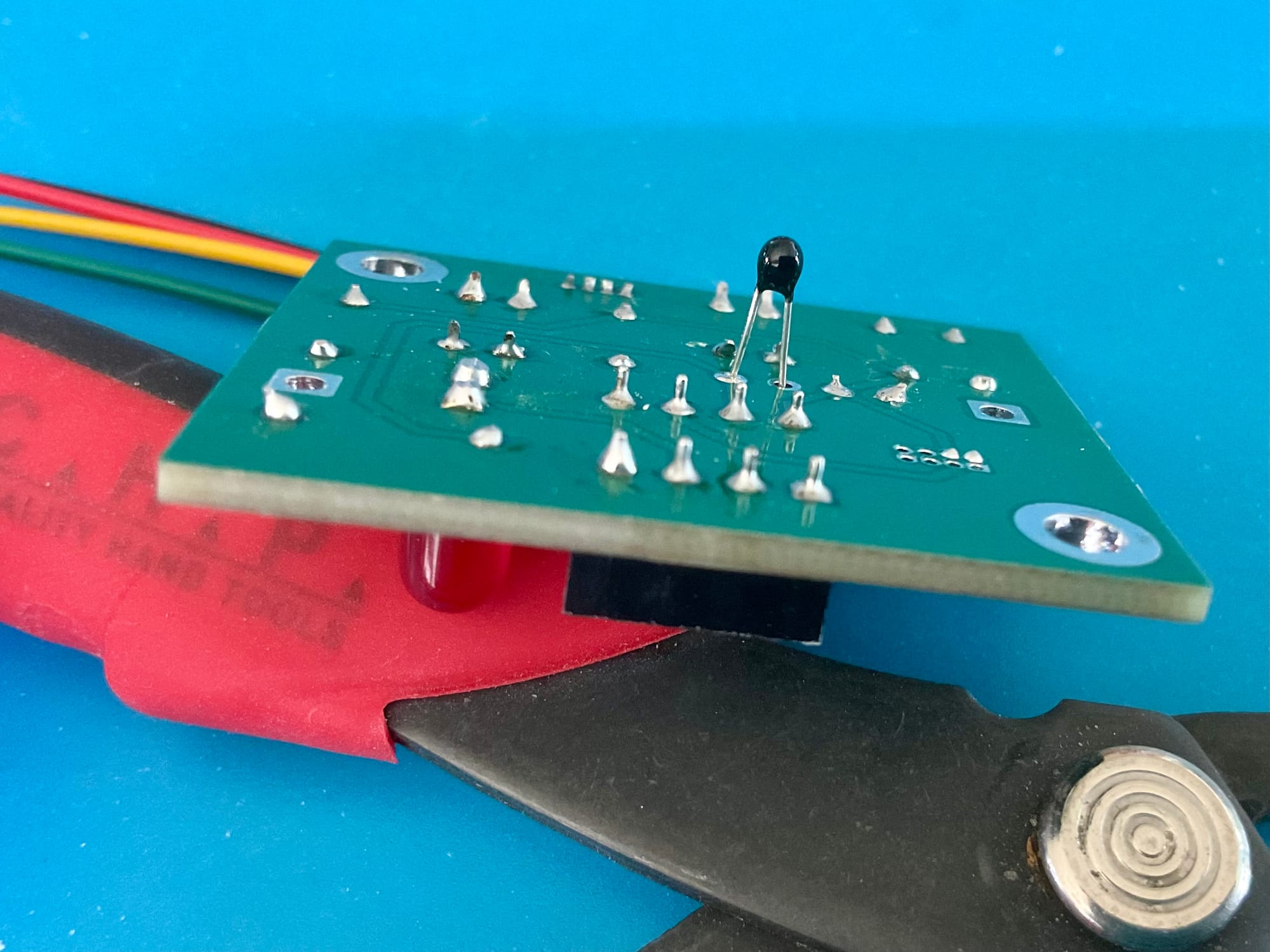
The communication lines on the RJ11 are galvanically isolated using the two optocouplers. Below a picture of the backside showing the NTC temperature sensor that will protrude from the housing to touch the cell.
You can find the circuit and PCB design in previous posts… search for “BMS” to find all related articles. Next I will see if I have all the parts for the controller board before starting with the software.