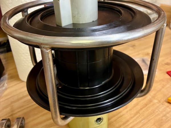
CNC vs 3D printing

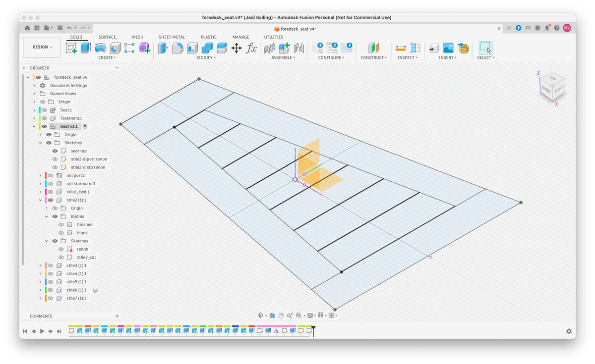
As expected, after learning a thousand things with the initial design and loading that on the CNC, I started over with the design of the seat to optimize the method. I started with a top view design of how it should look like as shown above. There’s the individual teak boards, this time I kept them spaced with a 1mm gap between them to accommodate slight variations in width and for now left out the slots, which I plan to mill after assembly.
Top left is the first of 9 stiles which is closest to the bow. It spans over the side rails so only has mortises for the rail tenons. Stile2 is the first one with tenons on each end that are angled to be perpendicular to the rails. So after extruding each board as separate components, I continue on stile2.
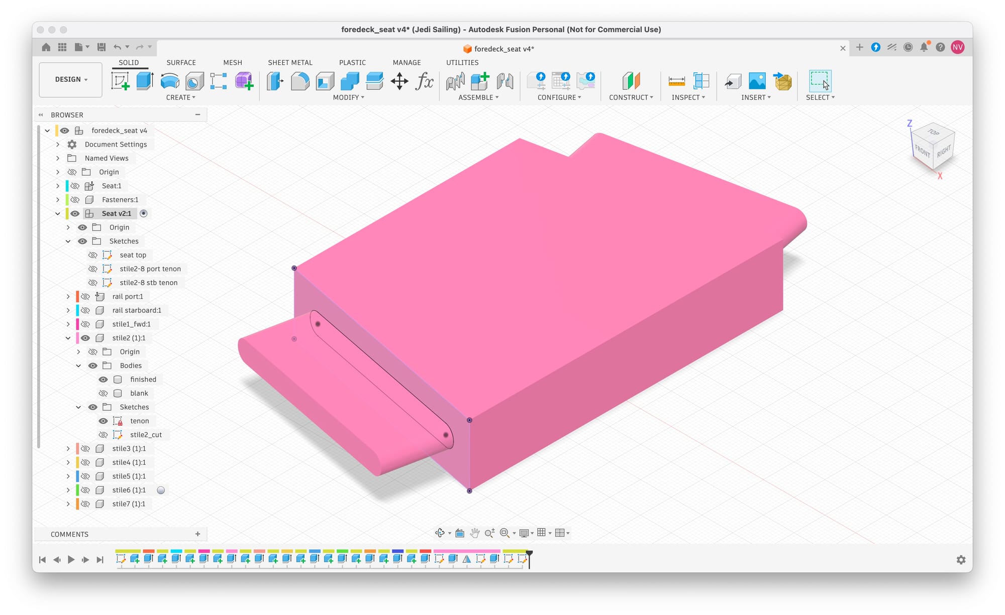
on the port side edge I sketch the tenon, maintaining a shoulder of 1/3 of the board thickness. After extruding it for a distance equal to the board thickness, I simply mirror it to the starboard side, which finishes this component.
But while I can 3D print that, I can’t CNC it. 3D printing is a form of additive manufacturing, while CNC is subtractive manufacturing where we cut the piece out of a larger blank. To create the cut file for the CNC router, we need to model the blank that we cut from as well.
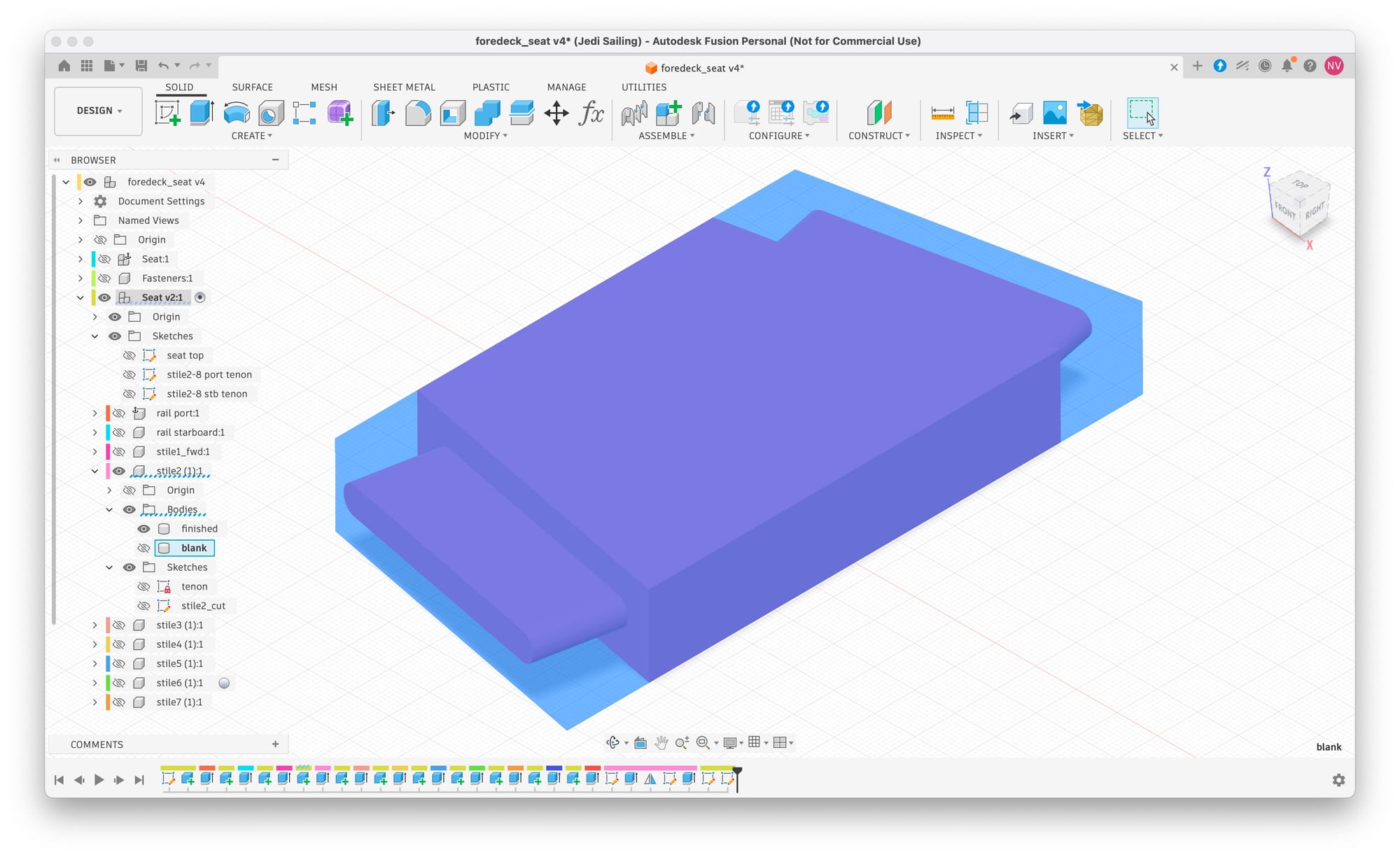
I do this using a second sketch, where I first project the finished stile as construction lines, then quickly draw a rectangle and add restraints for each side to be co-linear with the sides of the finished stile and the tips of the tenons. Extruding that as seen in the picture above produces a blank with mitered ends that the tenons can be cut from.
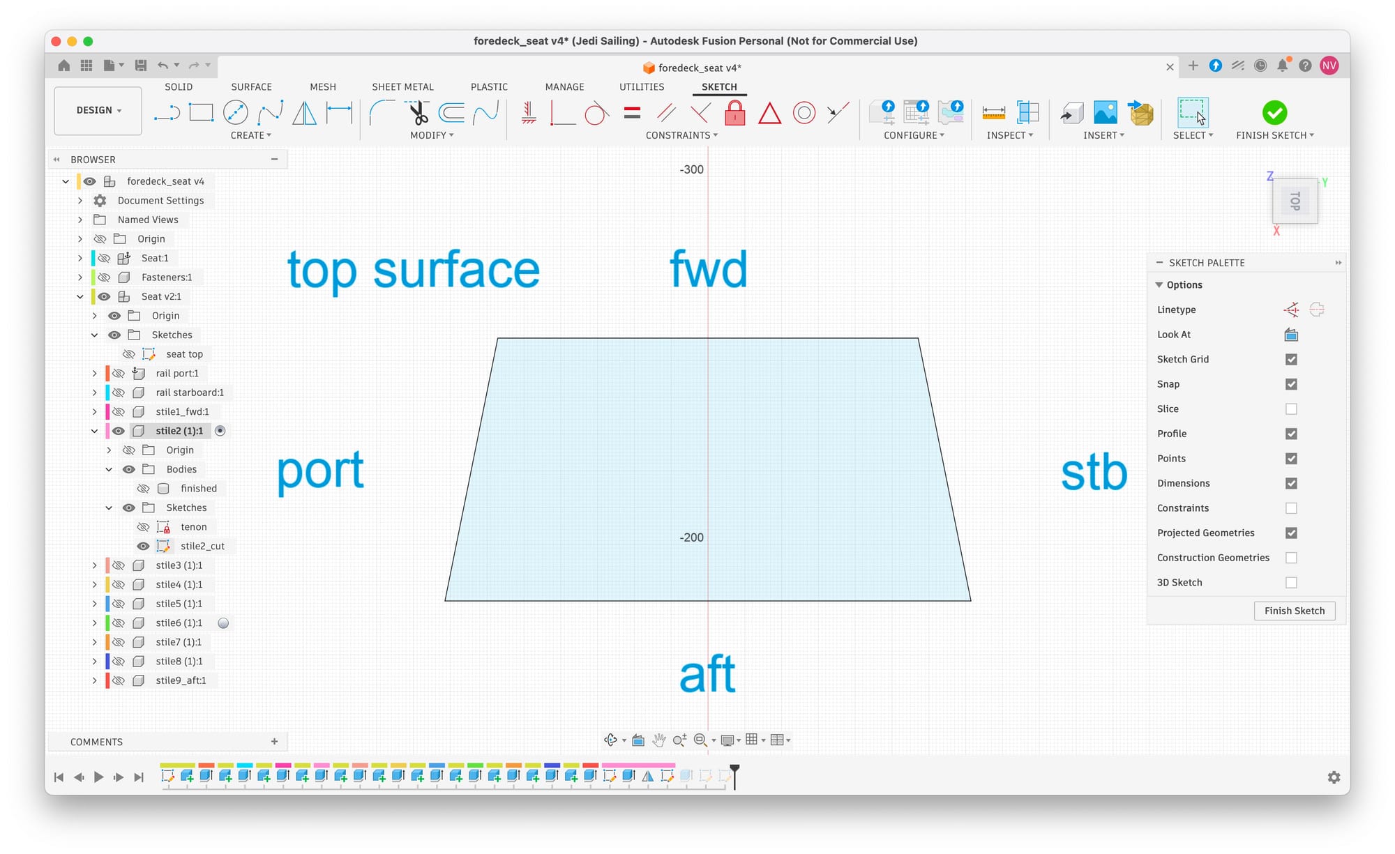
In the sketch for this blank I add text to aid with positioning the material and overlaying this cut file on the display of the Shaper Origin as part of the augmented reality view.
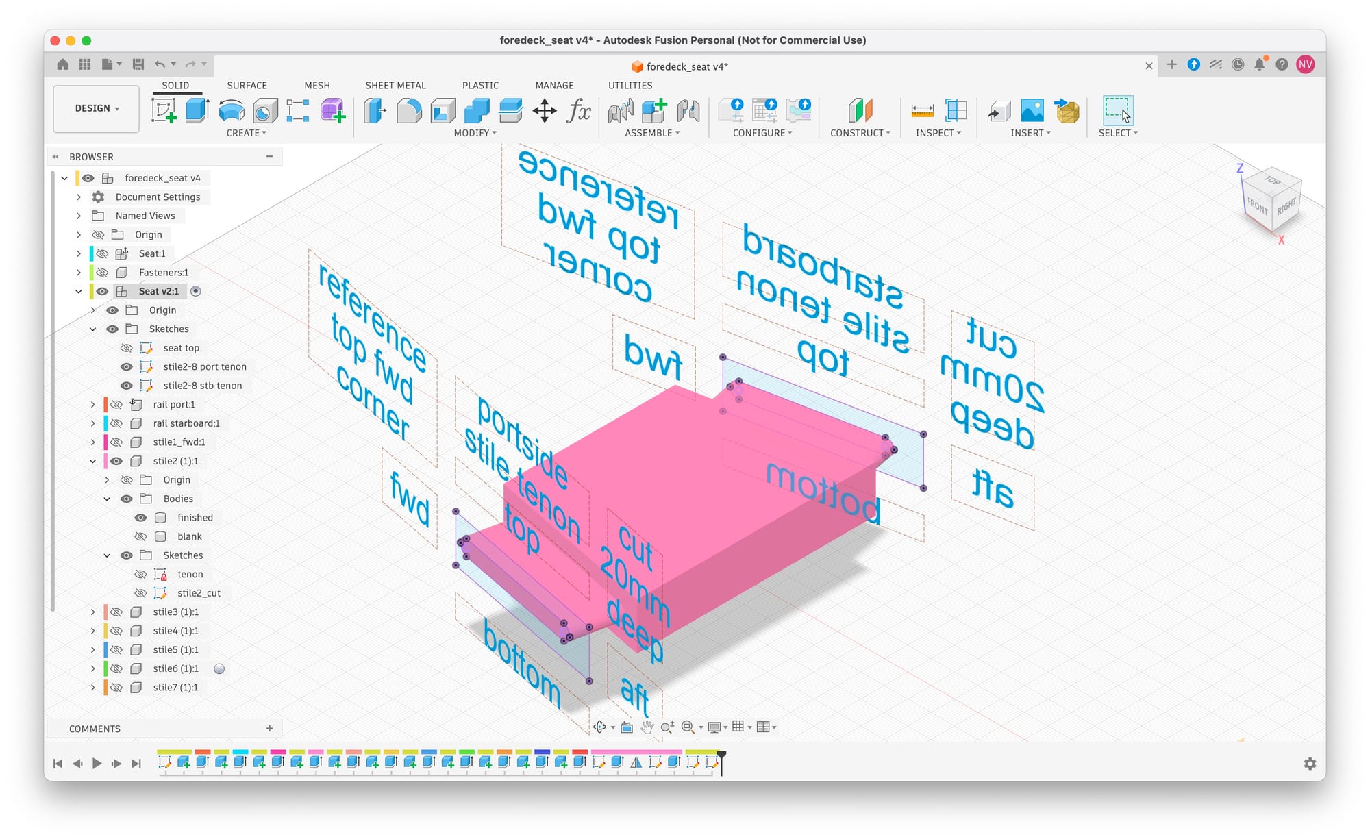
Next we need the cut files for the tenons at each end. I create the sketches on the mitered edges of the blanks, then project the tip of the tenon from the finished stile. Next I add lot of text to aid during the milling. In the picture below you can see how these two sketches match up with the tips of the tenons in a 3D presentation.
Besides how deep to cut, it’s also important to keep the reference surfaces consistent so that slight variations in board thickness and width end up at the same side.
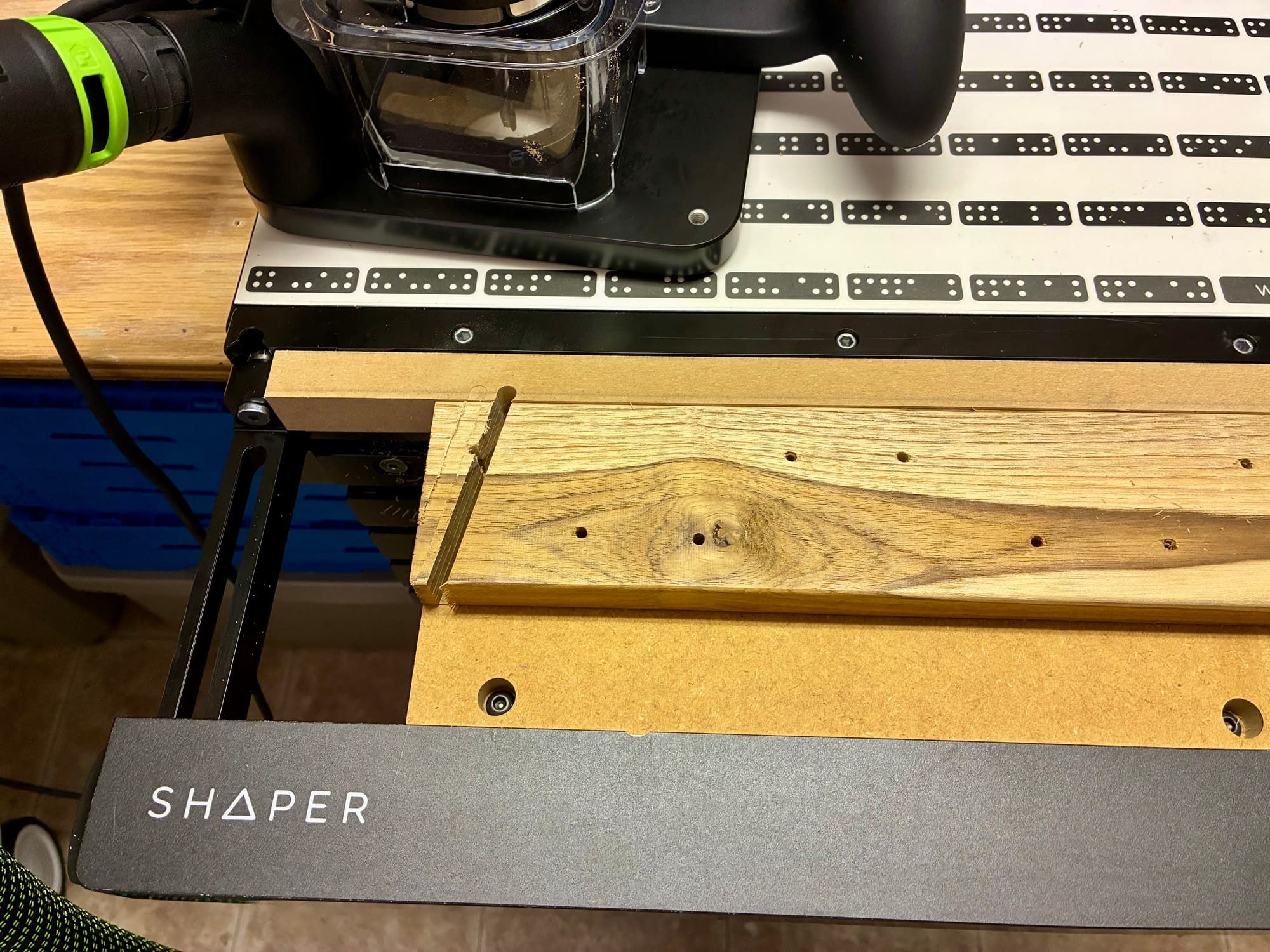
The last picture shows a trial cut I did for this design method. I do this on a board riddled with mounting holes that I planed the same as the boards that I will use for the build. I use the Shaper Workstation with the shelf. A spoil board behind it and the top of the shelve is a spoil board as well. I use double sided tape to keep the board in place. I will make pictures of the process during the production run 👍