DC high power design

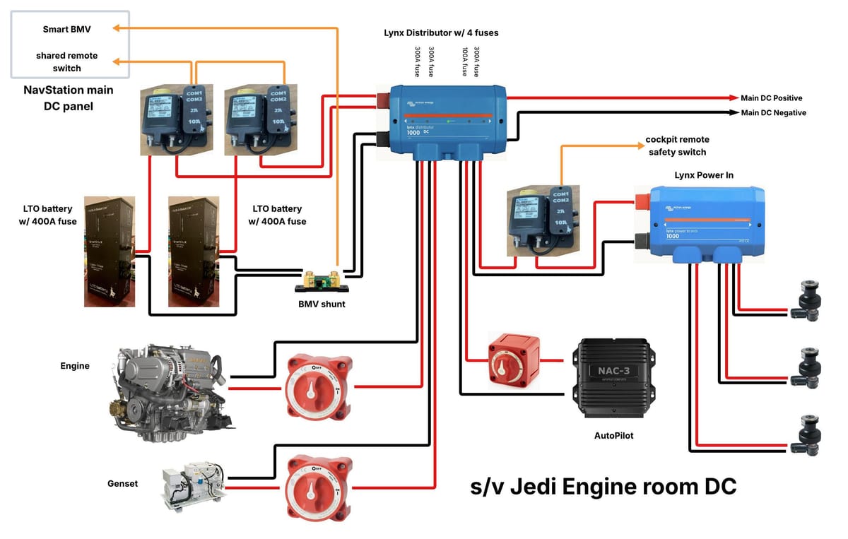
We have completed all the projects required for an update to the engine room high power 12V DC circuits. These projects were the new LTO battery, check the old AGM battery and design, test and build the cradle mounts for the BlueSea Systems Remote Battery Switches. We designed that to be able to daisy chain the remote ports with multiple switches, BMS’s, relays and multiple RBS’s.
In the diagram above I show two LTO batteries: as my old AGM tested good, we will use that instead of one of the LTO batteries. This also gives me a great out in case the LTO won’t start the Yanmar diesel, which many CruisersForum members seem to think (or hope :-). That battery is already hooked up and I successfully hoisted someone up the main mast with it so I think it’ll be fine but we keep the tension building for a little while longer.
Another step for me is the use of Victron Lynx products, which I never used before. Of course I use them differently than Victron imagined to adapt it to our setup. The diagram above is for the 12V part… we also have 24V but as of now everything connected is 12V so the 24V is just an empty Lynx Distributor.
Let’s go through the components: first at the top right is the power feed from our main busbars that we rebuild a couple years ago. We get 4/0 gauge cables for positive and negative which we connect to one of the horizontal connections of the Lynx Distributor, which Victron suggests are for interconnecting multiple Lynx modules, which we don’t do; we just want a connection without a fuse as this cabling is protected by a fuse even before the main busbars.
The left side of the horizontal connections are used for connecting our batteries. Here too we don’t use fuses because those are already part of the LTO battery. For the old AGM I use a MRBF fuse directly connected to the battery positive terminal.
Each battery does have its own battery switch but their remote ports are daisy chained to one switch that is on our new main DC panel at the navstation.
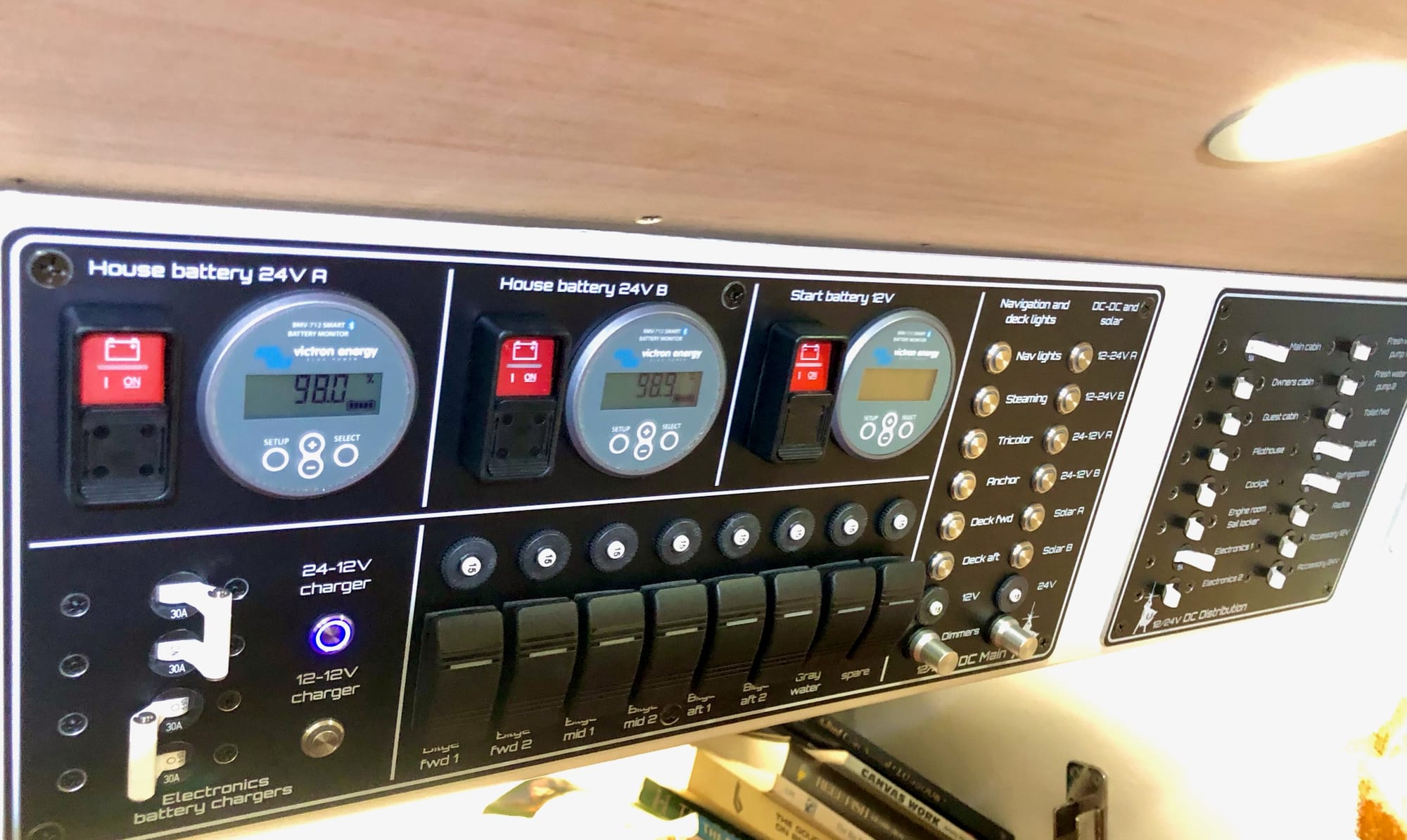
The LTO batteries have their own internal SmartShunt, but there’s also a SmartBMV that monitors both batteries, so their negative cables join each other at the shunt. The load side of the shunt has two cables to the Lynx Distributor. The use of two cables isn’t really necessary electrical-wise but a requirement for code. The shunt has a data cable back to the main DC panel where it’s display unit is mounted right next to the RBS remote switch (third one in the picture below)
This leaves us with the Lynx Distributor vertical connections. Each of these accept a MEGA fuse: we use 300A fuses for the main engine, the generator and the electric winches and a 100A fuse for the autopilot. The engine, generator and autopilot are plain simple as all they have is an isolation switch; the feed to the electric winches is a bit more interesting at there’s another RBS which has its remote switch in the cockpit. We normally disable the winches when not in use and now we can totally turn their power off to make it even safer.
After the RBS comes another Victron Lynx component, this time a Power-In which doesn’t have fuses, it simply splits the feed to three winches. In all the years aboard Jedi we never used two electric winches simultaneously so I don’t expect any trouble here. If we ever blow the 300A fuse, we can upgrade it to a 400A fuse as we use 4/0 gauge cabling for them, but it is much more likely that we upgrade the winches to 24V instead.
Which just leaves an endnote about these electric winches: these are all 30 years old and we are in the process of serious maintenance which includes new bearings, new seals etc. we hope this is the extent of the repairs needed but if we find more damage that requires significant parts replacement, this often includes the motors and of course that triggers an early upgrade to 24V for all of them.
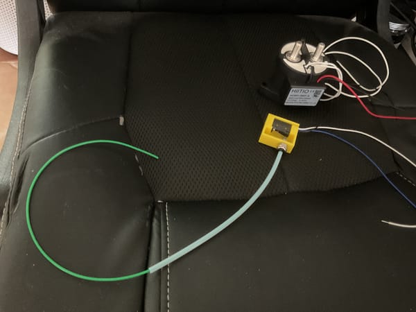
I am in the process of designing a new control module for the winches as we recently had another failure of a switch that left a winch running until we flipped the safety switch. For this module I selected a solenoid that supports 12-36V control voltage so that we don’t have to replace it when changing voltage, but I am also designing a better switch to operate the winches, using the 3D printer of course!