Engine control box

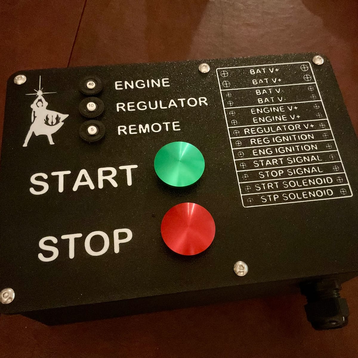
We have had an engine control box in the engine room for the past 10 years and have learned that this is an item every cruiser should have. The main functions are assisting start and stop of the engine, connecting the alternator regulator, the original engine control panel (if not replaced by NMEA2000 interface) and a new remote control panel at the steering station. The box has three DC breakers and is fed power from the engine isolation switch which is right next to it.
We had our start relay fail twice: the first time I had to use a screwdriver at the start solenoid to start the engine and this triggered me making the control box so that the second time the relay failed I could simply push the start button on this box instead of letting sparks fly at the solenoid.
For starting and stopping the engine, the box has two heavy duty relays that connect the 40A breaker output directly to the start- and stop solenoids on the engine with proper size wiring, replacing any OEM relays like the start relay on our Yanmar 4LH-HTE. The relays used are rated for 120A and by mounting them separately from the engine, vibration is all but eliminated, greatly extending the lifespan of the relays.
Each relay also has two flyback diodes: one for the coil of the engine solenoid and one for the coil of the relay itself. These diodes also extend the reliability and lifespan of both the relays and the start/stop switches used.
Last but not least, there are two heavy duty push button switches for starting and stopping the engine. These switches are parallel to the relay contacts, i.e. they bypass the relays so that the engine can be started and stopped even when a relay fails.
Note that our start solenoid uses 50A initially, then 17A during cranking. The stop solenoid only uses 2.5A and Yanmar didn’t add a relay for that, but I want a remote panel with just signal wiring so added a relay for stop and the same big one as for start so I can swap them out if ever needed.
For the regulator there are three main wires: a DC negative, a DC positive which has a separate 10A breaker and an ignition wire. You can jumper this ignition wire to the engine ignition wire, but our remote panel has an additional switch in series so that the alternator can be turned off while using the engine.
We plan to replace our Yanmar panel in the future but for now we still have it, mostly for the gauges and alarms. This control box intercepts three wires coming from the panel to the engine: the ignition wire, the start signal and the stop signal. This box will backfeed the ignition wire to the Yanmar panel so that it will come on even without a key inserted. The start and stop signals are used to control the relays.
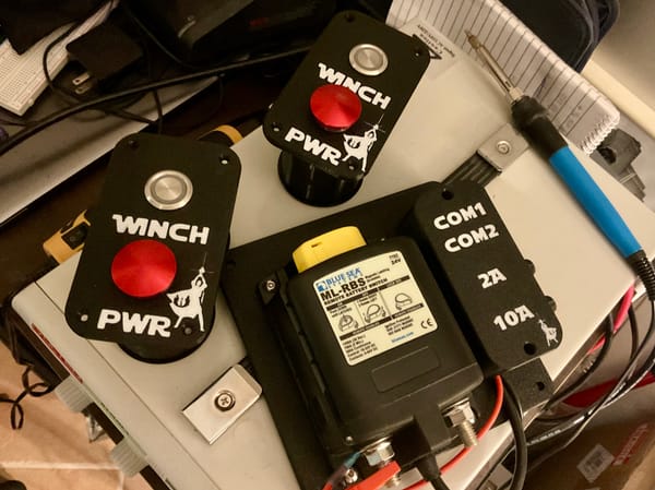
The box has a 6-pin connector for a remote panel, which is still in the pipeline. That panel will be small and right at the steering station in the cockpit. It has two latching switches for ignition and regulator, two momentary switches for starting and stopping the engine and a remote switch for power to the windlass which is unrelated to this control box.
The 6 conductors in the control cable: +12V from a dedicated 5A breaker, DC negative, engine ignition, regulator ignition, engine start signal and engine stop signal.
The breakers and switches are large and mounted on the front panel. The housing has some panel supports at the breaker and switch positions to support the front panel when breakers are reset or switches are pressed.
The DIN rail has two large terminals (max 6AWG), 11 medium terminals (max 10AWG) and two end clamps to keep everything tight. There are three busbars installed (the red pieces) to link terminals to accommodate more wires.
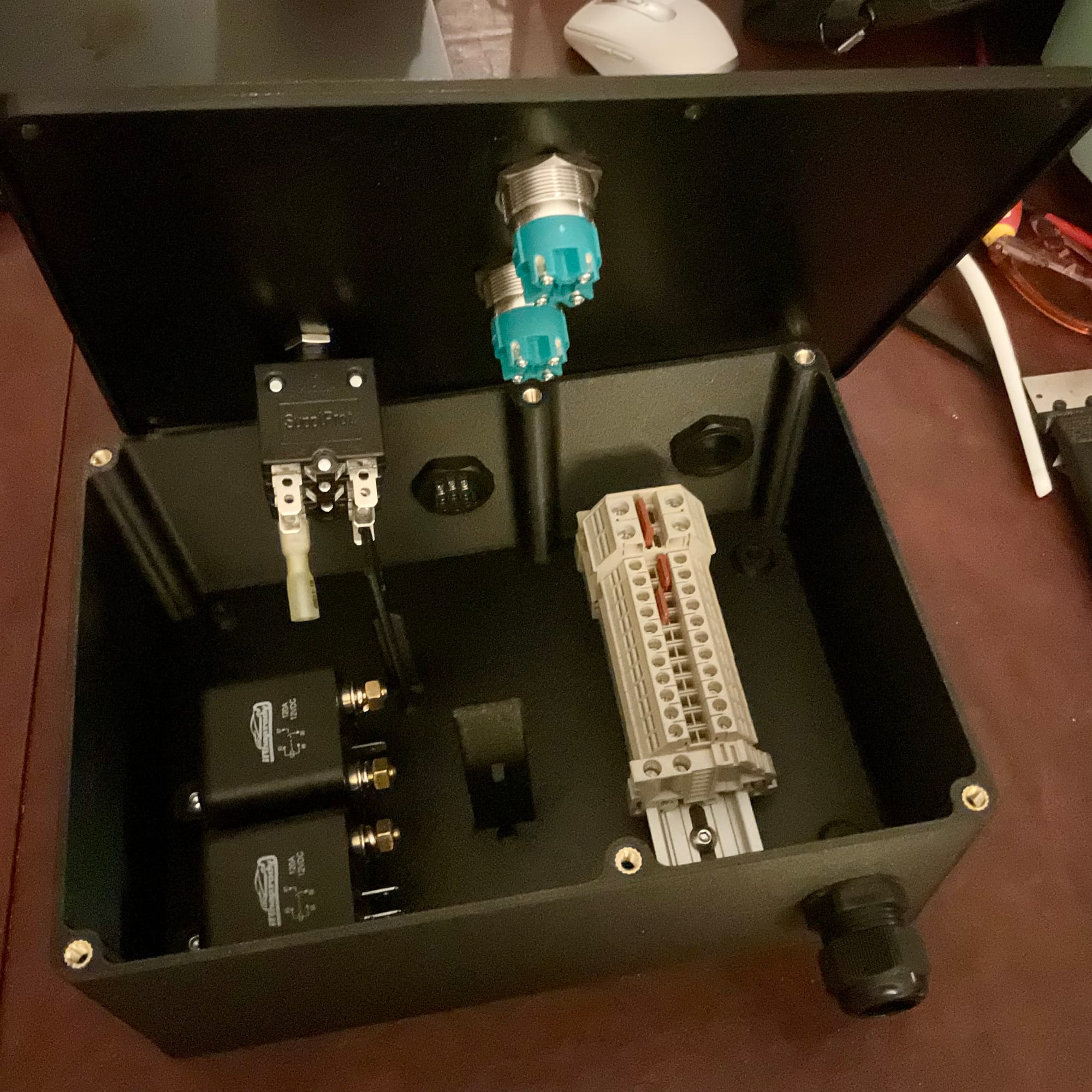
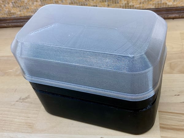
This is a large box, near the limits of my 3D printer. As I print my electrical boxes in polycarbonate (because it is fire resistant), I had zero hope that I could print this large housing without warping issues. To make this possible I bought a new filament: Tanmorry PC-GF, glass fiber reinforced polycarbonate. Where regular polycarbonate shrinks 0.5% during cooling, this glass fiber reinforced version only shrinks 0.06% and the print came out great. Including lid the overall dimensions are 236 x 172 x 96mm (I use 3mm wall thickness). I used a 0.6mm nozzle for the housing and a 0.4mm nozzle for the lid which is printed in regular black and white polycarbonate.
I also used 12 M5 heat-set inserts for mounting the relays, the DIN rail for the terminals and for the lid.
Now all I have to do is wire it :-)