Lewmar ELS system

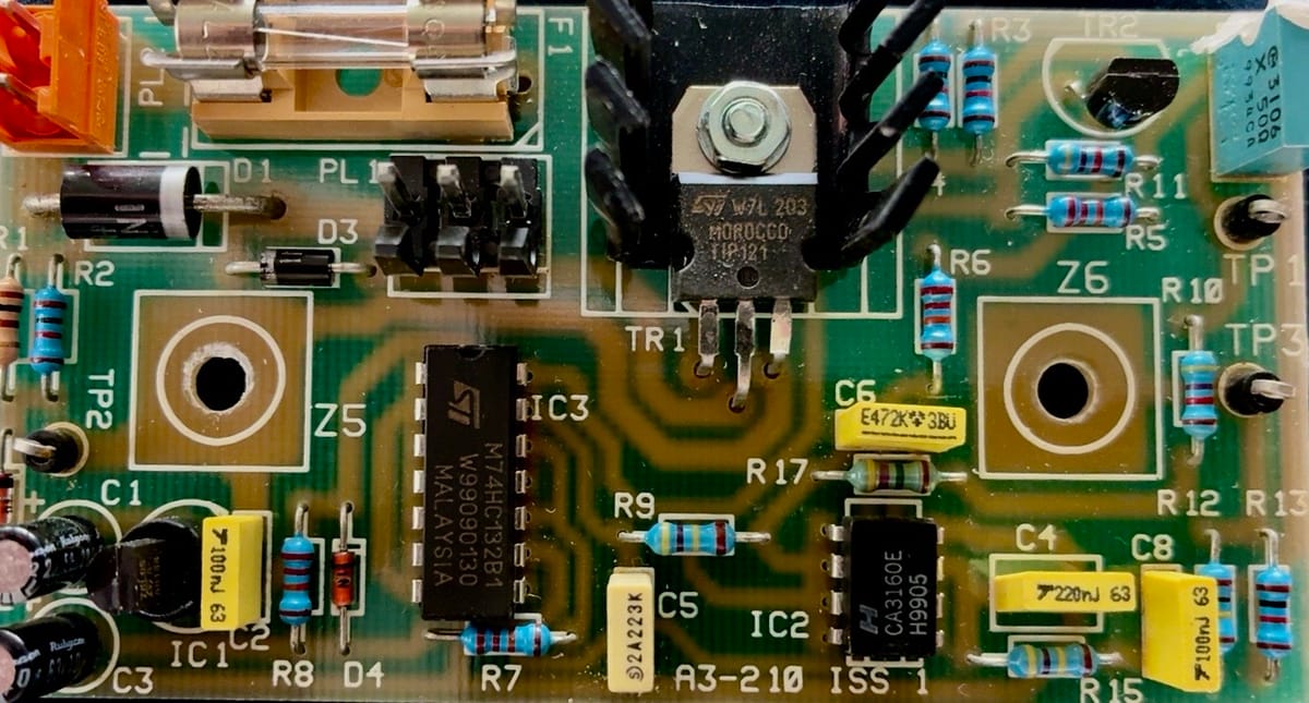
The Lewmar winches size 55 and up must have this Electric Load Sensing module while it is available as an option for smaller models. For Jedi it means we have these on our model 58 and the two 66’s.
The ELS monitors the current to the winch and interrupts when it is deemed too high. This limits the mechanical load that the winch handles as well as protects the fuse or breaker from tripping as the ELS is much faster acting. As both positive and negative cables go through the ELS module, it must have a contactor for switching it on/off as well as a shunt to measure current.
Unfortunately these modules are different for each model winch and also for 12V vs 24V models. As we are upgrading our 58 from 12V to 24V, this module has my immediate attention. Luckily I happen to be an EE from the ‘80’s and ‘90’s which is what my ELS modules are as well, so I am instantly familiar with every component as well as the design philosophy behind it. A first quick observation shows me that this same board can work for every winch and for both 12V and 24V.
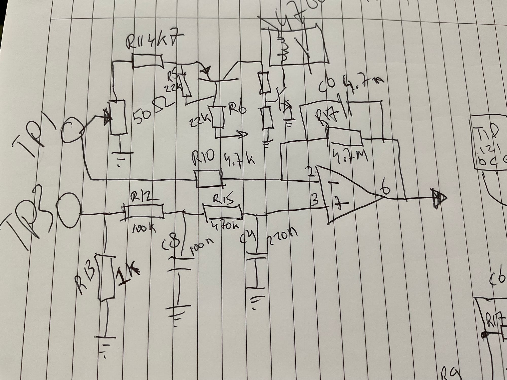
My first step is to reverse engineer the part of the circuit that deals with measuring current and deciding if it’s too high or not. I use detailed photos of front and back of the simple PCB and make a quick drawing of the part that interests me.
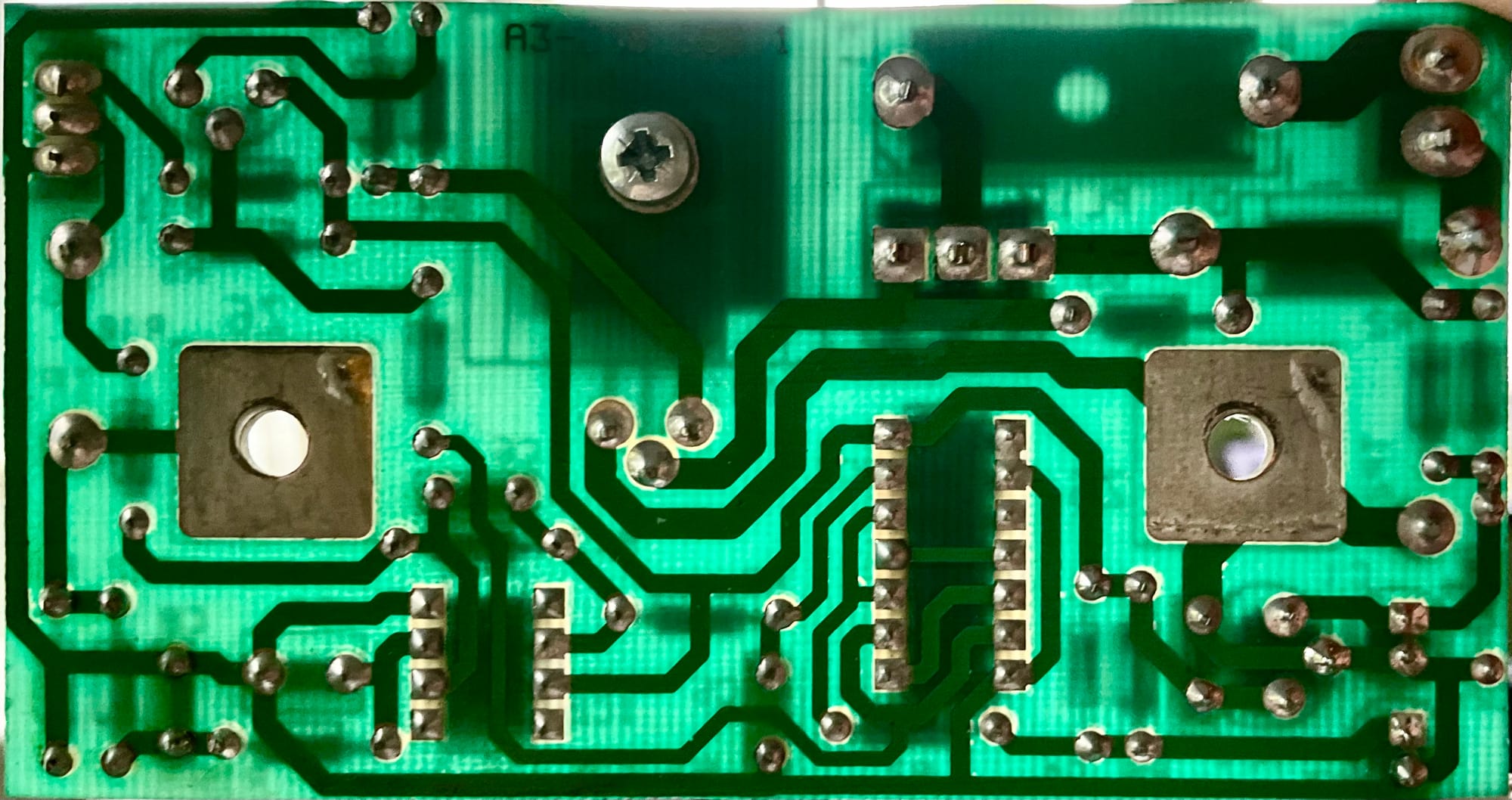
The two large pads are where the shunt connects. One side is DC negative and also has test points TP2. The other side has TP3 and has the small voltage that represents the current through the shunt. TP1 is next to a precision potentiometer so must be the calibration voltage for the circuit.
So what I find is first a second order low pass filter to clean up the input from the shunt. This is fed to an OPAMP which has 1000x amplification as per R10/R17 with C6 bypass capacitor suppressing amplification for any leftover AC. The reference voltage from the potentiometer is fed to the inverting input of the OPAMP, making a classic comperator circuit: if TP1 is higher than TP3, the output switches off.
There’s something going on with the feed to the potentiometer as there’s some transistors involved which also switch the contactor using the input voltage. The rest of the circuit is 5V from a voltage regulator that can handle 30V input.
First actual test is the shunt itself. It appears to be a piece of tinned copper and that’s exactly what it turns out to be, with a 70 micro Ohm resistance, so very low. Below my testing where I put 10, 15, 20, 25 and 30A through it while measuring voltage drop:
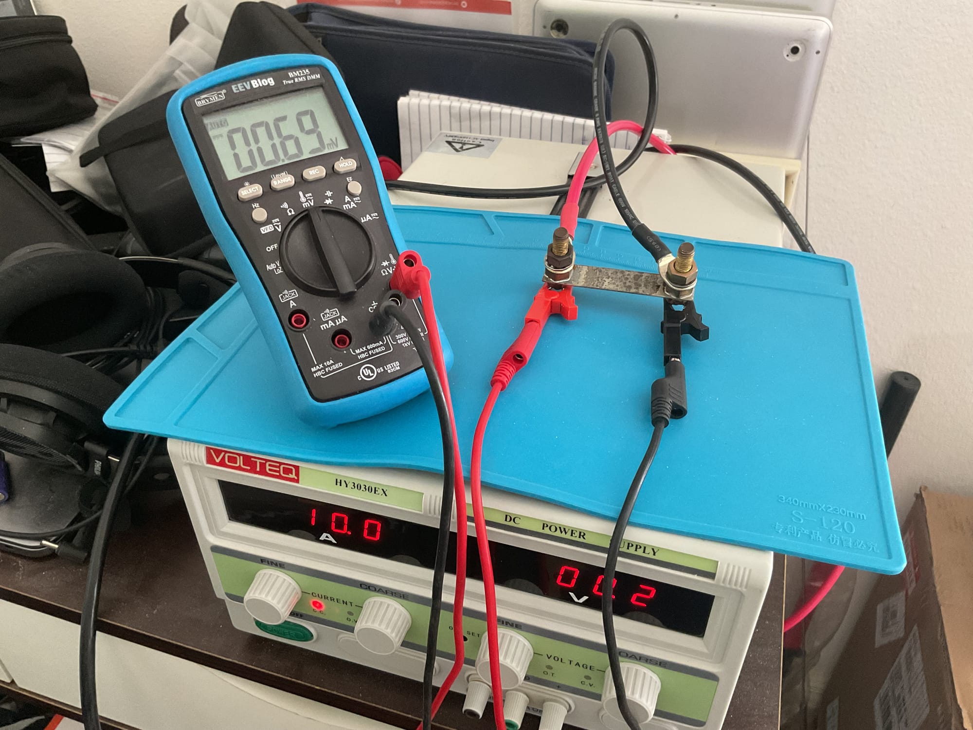
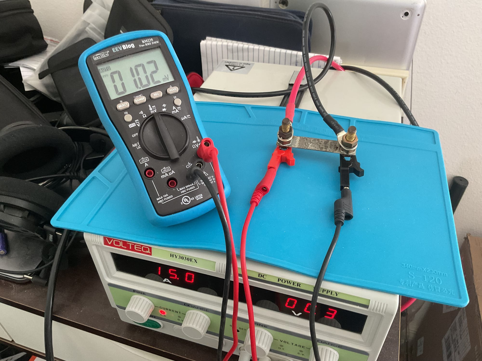
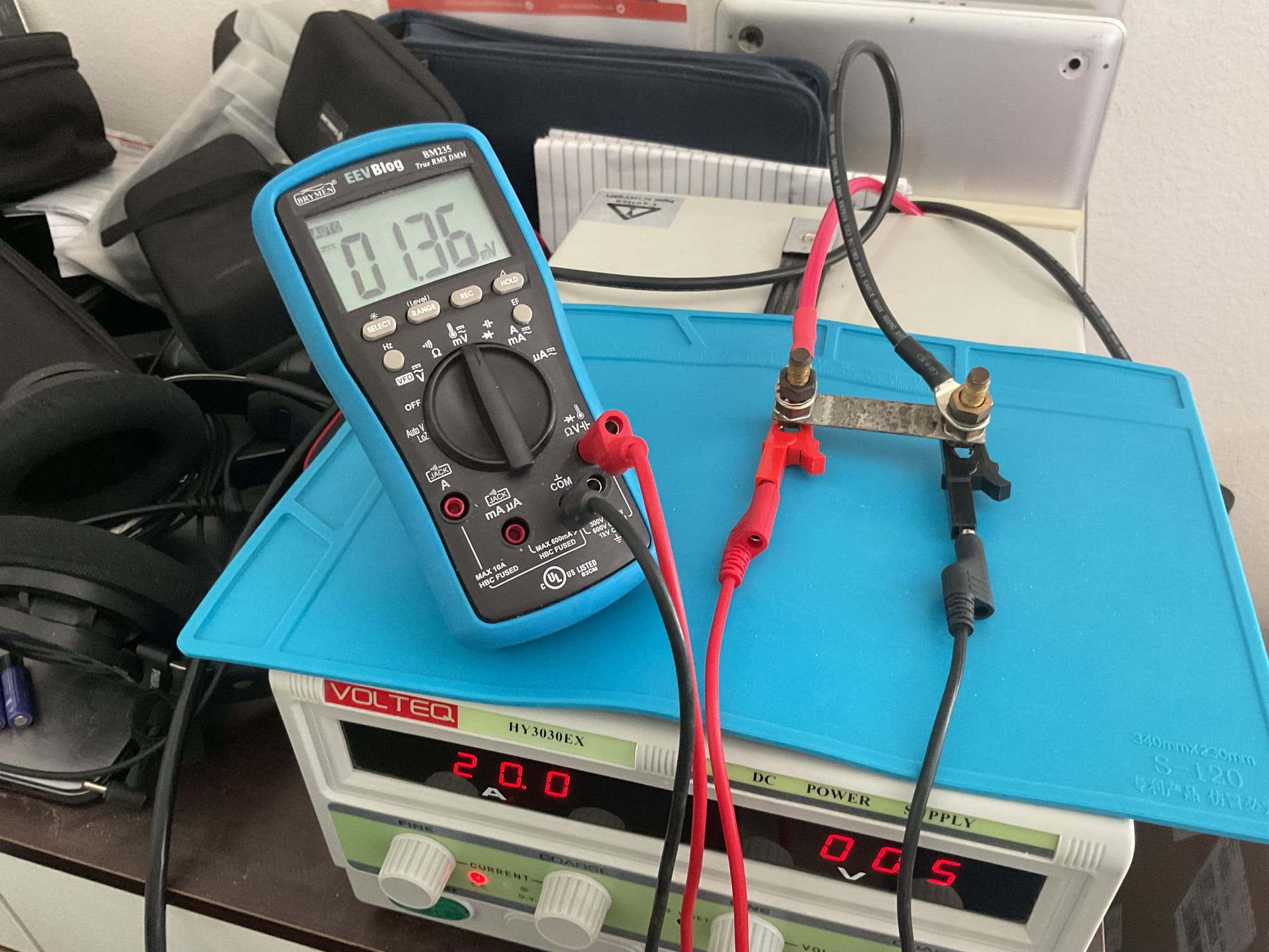
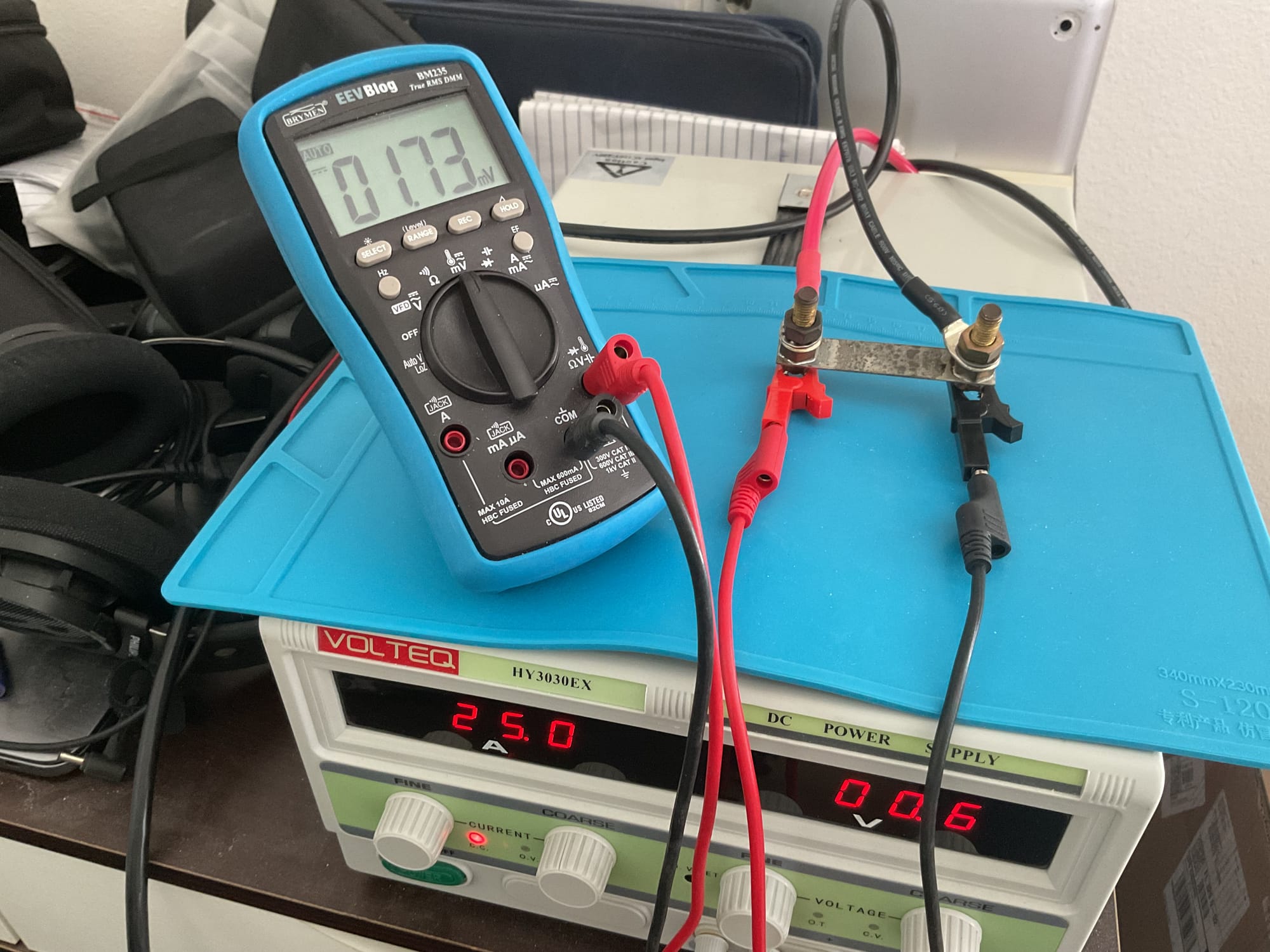
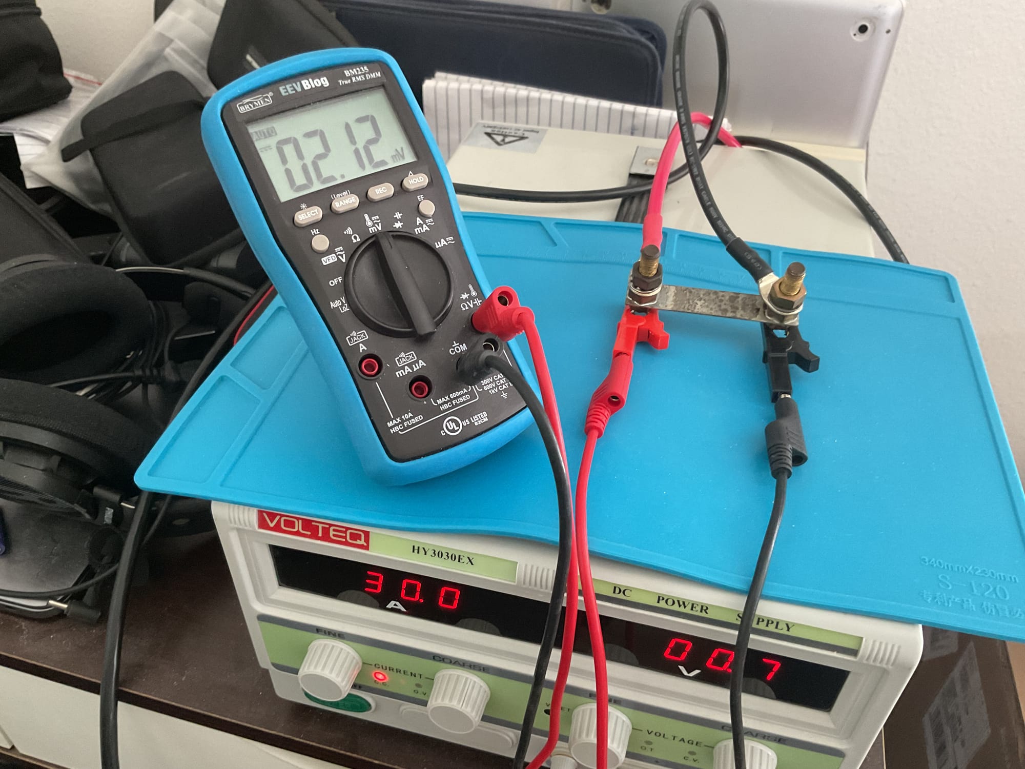
Note that I am using my Volteq 3030 in constant current mode with the shunt across its high current terminals on the back, effectively shorting it. The current readout is very precise but we know that a shunt always has easy numbers and here we see that 15A shows 1mV and 30A shows 2mV to confirm this.
for confirmation I measured length, width, thickness, diameter of the studs and center to center distance of them and asked ChatGPT for the resistance if it’s copper and it came up with within a micro Ohm of these measurements.
Next we need to know the voltage at TP1. The power design of the circuit is remarkably elegant: it is only powered when you press the winch button. So I connect a new contactor that works from 9-30V, set my Voltec to 12.0V, connect negative to TP2 and positive to the switch connector. The contactor engages and I measure 21.4mV at TP1.
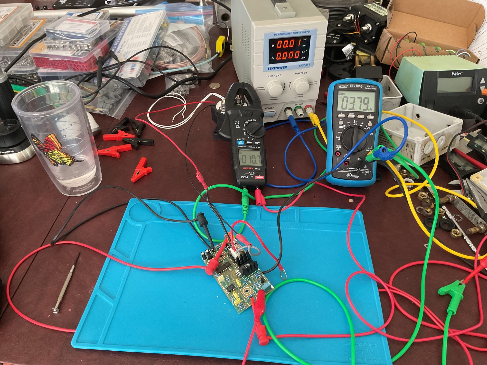
A quick calculation is 21.4 x 15A = 321A. I expect it to switch off at about that current the TP1 voltage drops! This is that something going on with the transistors and the raw input voltage. When voltage is higher, it allows for less current, kind of limiting to a power level instead of current level. 12.0 x 321 = 3.85kW.
Also, when it trips, it doesn’t come back on unless you release the winch button and press it again, basically turning the ELS off and back on. I see in their documentation that they call this “smart auto reset” hahaha.
In the picture above I have changed the reference voltage to 10.7mV and the power supply to 24.0V and of course now it trips at around 11mV shunt voltage which is 165A or 3.96kW. I should reduce it a bit more.
All this also has to do with the fuses or breakers used, as well as the type of batteries. For the fuses we need to check the trip curve to see if we risk blowing a fuse before the ELS acts. For the batteries, lead acid batteries have a significant voltage sag under load, while the AGM TPPL batteries were much better and lithium tops even that. As we have switched to 24V LiFePO4 house batteries and now LTO 12V batteries, we have virtually no voltage sag at these high currents. I will start with a 250A MEGA fuse to power both 12V Lewmar 66 winches (never used simultaneousl) and a 100A MEGA fuse for the 24V Lewmar 58.
I have always used 225A ANL fuses to these winches and never had one trip. Now that we know that the ELS does a very rapid cutoff at a maximum of 350A, we can look at the trip curve for the ANL fuses:
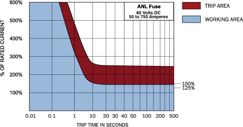
We see that a 200% load which would be 450A with our 225A fuses, wouldn’t trip it for several seconds. As the ELS is much faster acting, this was great.
Now that I fuller understand the ELS and found that it is a solid product, i think it’s safe to consider the fuse more to protect the cabling used and let the ELS and the thermal protection of the motor deal with the winch itself.
I did look at the current ELS offered and see it uses a different internal fuse so they did update the design a bit but it feels like the exact same functionality. So these are now added to my future project list where I will use something like an INA226 power sensing chip with ESP32 microcontroller to do this, while of course using the SensESP library to integrate it with a SignalK server if available. It would be much better as it will have a web server for adjusting its settings, can control the popular RBS battery switches to turn the winches completely off and even allow a curve instead of just a limit setting for an even safer winch operation.