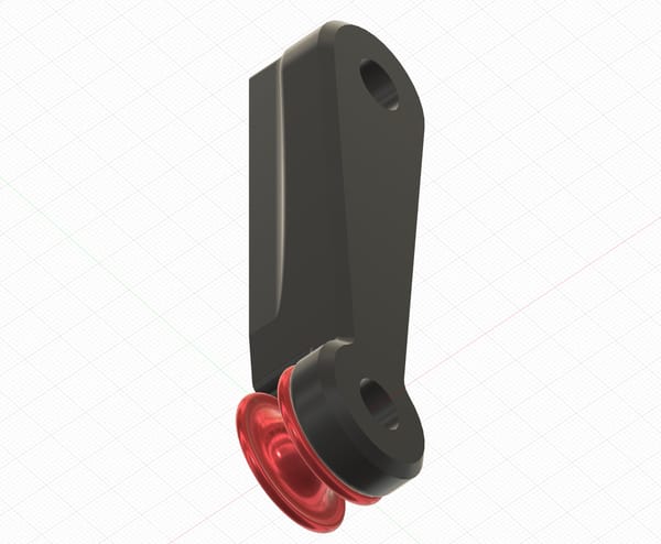
RBS cradle

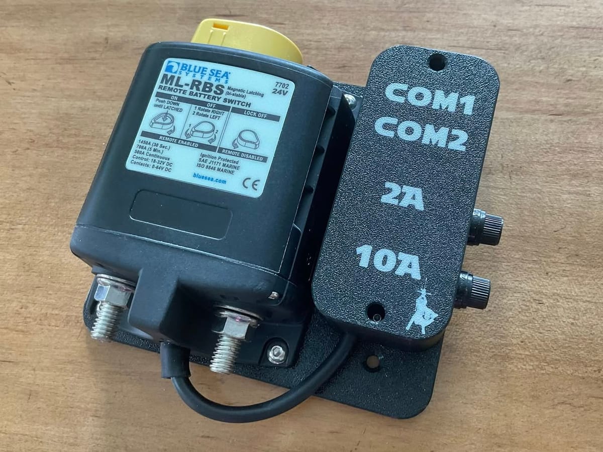
I designed a mount for the Blue Sea Systems Remote Battery Switch (RBS) that includes a junction box, fuses and communication ports for remote control.There are two RJ11 modular jacks that can be used in a daisy chained configuration that includes multiple RBS modules, multiple remote switches and multiple microcontrollers for programmable control.
The simplest setup: use one remote switch to control two RBS modules. The first RBS has a 4-conductor phone cable to the second and the second has the additional connector in use for the link to the switch.
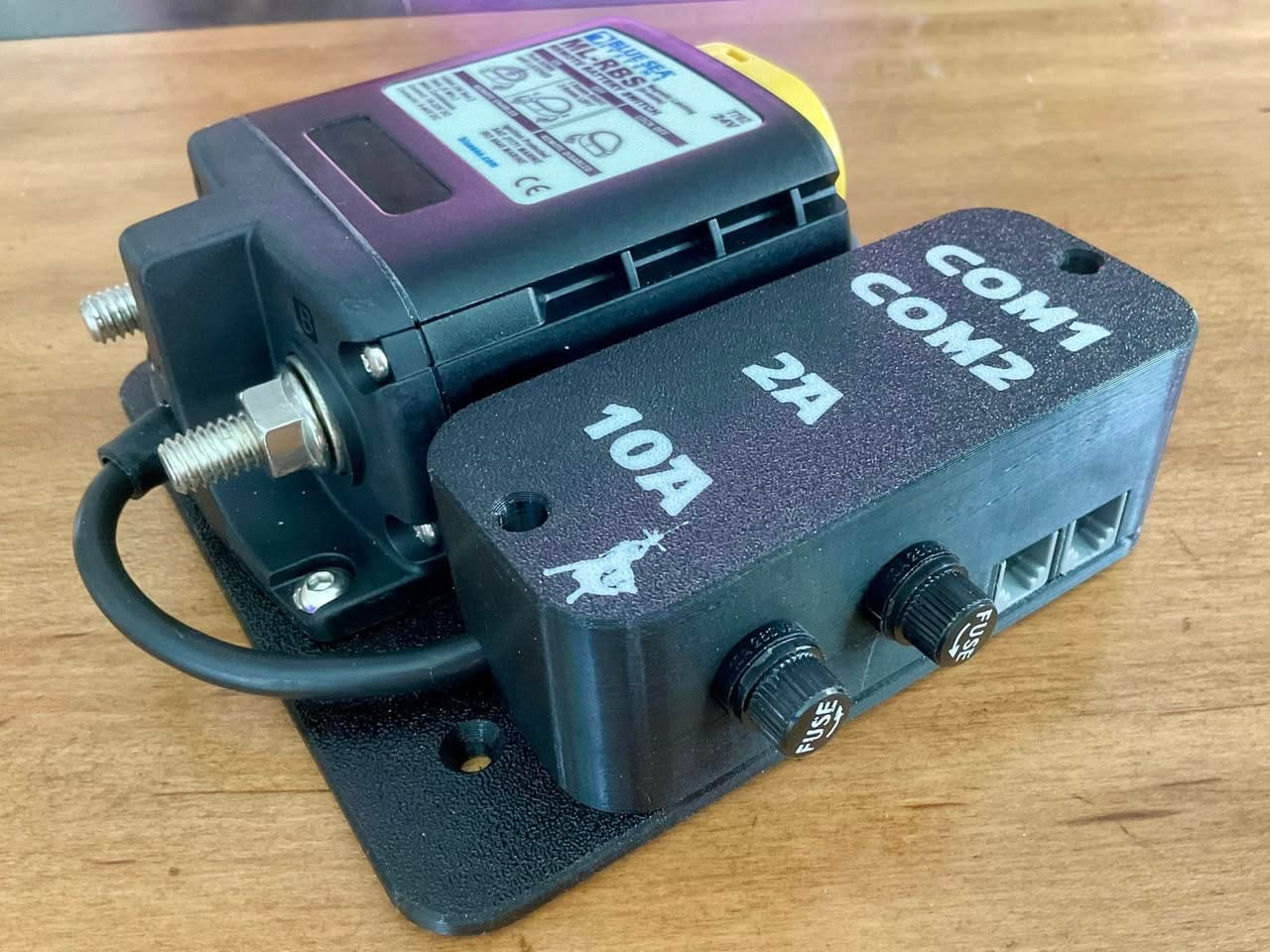
The control cable from the RBS goes into the bottom of the junction box. There will be two additional 16-gauge wires coming from the junction box: a positive that normally goes to the big RBS terminal that is always on and a negative that goes back to the battery or busbar. This is the power supply for remote operation. The two fuse holders are connected to the 16-gauge positive wire that goes to the always-on power. The output from the 10A fuse connects to the +Ve conductor of the RBS control cable. This is the power supply for the coil that moves the contactor inside the RBS. The 2A fuse output first has a Schottky diode, then connects to the power pin of the Com ports. The -Neg conductor of the RBS control cable connects to the black 16-gauge wire that comes from the junction box. It is used for the 10A coil power as well as for the remote status feedback. Whenever the RBS is switched on, it pulls the yellow conductor of its control cable low, to the -Neg that we connect to the 16-gauge wire. This yellow conductor is also connected to the communication ports and used for lighting a remote status LED, or feeding an optocoupler to a microcontroller so that it knows the status.The RBS control cable also has two conductors that are normally connected to a momentary switch: one to make it switch on and the other to make it switch off. The momentary switch (or miniature relay if microcontroller) connects those conductors to the +Ve that we connect to the Com ports.The Schottky diode prevents back feeding when multiple RBS units are connected to the bus. When you mix 12V and 24V RBS units then remove the 2A fuse from the 24V units. The RBS units get their correct voltage from their 10A fuses and a 12V control voltage from the remote switch is more than enough to control them (even 5V works).While we normally switch a positive conductor, sometimes I switch a negative, for example for the windlass. In that case the black 16-gauge wire connects to the big terminal that is always “on” and the red must go to a power feed that has a 15/16A fuse or breaker.Switching the negative is used to prevent galvanic corrosion. Besides the windlass, another option is to disconnect the engine block from DC negative.